Chrysler 300/300 Touring/300C, Dodge Magnum. Manual - part 1265


  Index      Chrysler     Chrysler 300/300 Touring/300C, Dodge Magnum - service repair manual


Search            


Content   ..  1263  1264  1265  1266   ..


Chrysler 300/300 Touring/300C, Dodge Magnum. Manual - part 1265


3.

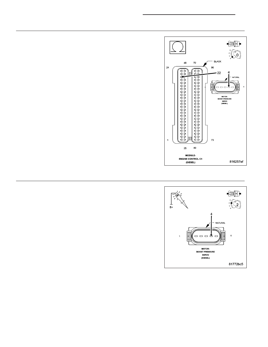
(X635) BOOST PRESSURE SERVO MOTOR CONTROL OPEN OR HIGH RESISTANCE

Turn the ignition off.

Measure the resistance of the (X635) Boost Pressure Servo Motor Con-
trol circuit between the Boost Pressure Servo Motor harness connector
and the Engine Control Module (ECM) harness connector.

Is the resistance below 10.0 ohms?

Yes

>> Go to 4

No

>> Repair the (X635) Boost Pressure Servo Motor Control cir-

cuit for an open circuit or high resistance.

Perform the ECM Verification Test Ver. 1. (Refer to 9 -
ENGINE - DIAGNOSIS AND TESTING)

4.

BOOST PRESSURE SERVO MOTOR

Turn the ignition off.

Connect the Engine Control Module (ECM) harness connector.

Turn the ignition on.

With the scan tool, actuate the Boost Pressure Servo Motor (Boost
Pressure Actuator) to 100%.

Using a 12 volt test light connected to 12 volts, check the (X635) Boost
Pressure Servo Motor Control circuit in the Boost Pressure Servo Motor
harness connector.

NOTE: The test light should be illuminated and bright. Compare
the brightness to that of a direct connection to the battery.

NOTE: The circuit will remain actuated by the controller for 30 sec-
onds. Be certain the actuation is active when checking the circuit.

Is the test light illuminated and bright with the actuation at
100%?

Yes

>> Replace the Boost Pressure Servo Motor in accordance

with the Service Information.

Perform the ECM Verification Test Ver. 1. (Refer to 9 - ENGINE - DIAGNOSIS AND TESTING)

No

>> Go to 5

9 - 1084

ENGINE ELECTRICAL DIAGNOSTICS - DIESEL

LX

5.

ENGINE CONTROL MODULE (ECM)

Using the wiring diagram/schematic as a guide, inspect the wiring and connectors between the Boost Pressure
Servo Motor and the Engine Control Module (ECM).

Look for any chafed, pierced, pinched, or partially broken wires.

Look for broken, bent, pushed out or corroded terminals.

Refer to any Technical Service Bulletins that may apply.

Were any problems found?

Yes

>> Repair as necessary.

Perform the ECM Verification Test Ver. 1. (Refer to 9 - ENGINE - DIAGNOSIS AND TESTING)

No

>> Replace the Engine Control Module (ECM) in accordance with the Service Information.

Perform the ECM Verification Test Ver. 1. (Refer to 9 - ENGINE - DIAGNOSIS AND TESTING)

LX

ENGINE ELECTRICAL DIAGNOSTICS - DIESEL

9 - 1085

P0069–MANIFOLD PRESSURE/BAROMETRIC PRESSURE CORRELATION

For a complete wiring diagram Refer to Section 8W.

Theory of Operation

The Barometric/Atmospheric Pressure Sensor is calculated from the Inlet Pressure Sensor Signal. The ECM com-
pares the signal of the Inlet Pressure Sensor to the signal of the Boost Pressure Sensor during low engine rpm
(non-turbocharger boost conditions) to determine the plausibility of these sensors.

When Monitored:
Engine speed is below 720 RPM. Intake Air Temperature is between 9.96°C and 84.9°C. There are no Sensor
Reference Voltage DTC’s. There are no other Boost Pressure related DTC’s. There are no Inlet Pressure Sen-
sor DTC’s.

Set Condition:
The difference between the Boost Pressure Sensor Signal and the Atmospheric/Barometric Pressure Sensor
Signal is greater than 150 hpa (2.175 psi.) for at least 6.0 seconds.

Possible Causes

BOOST PRESSURE SENSOR RELATED WIRING & CONNECTORS

BOOST PRESSURE SENSOR

INLET PRESSURE SENSOR RELATED WIRING & CONNECTORS

INLET PRESSURE SENSOR

ENGINE CONTROL MODULE

Always perform the Pre-Diagnostic Troubleshooting procedure before proceeding. (Refer to 9 - ENGINE -
DIAGNOSIS AND TESTING).

Diagnostic Test

1.

CHECK FOR ACTIVE DTCS IN THE ECM

NOTE: Verify and note actual Atmospheric/Barometric pressure.
Ignition on, engine not running.

With the scan tool, Clear DTCs in the Engine Control Module (ECM).

Monitor the scan tool for at least two minutes.

Cycle the ignition key off and on several times, leaving the ignition on for at least 10 seconds at a time.

Turn the ignition on.

With the scan tool, select View DTCs.

Is the status Active for this DTC?

Yes

>> Go To 2

No

>> Refer to the *CHECKING FOR AN INTERMITTENT DTC Diagnostic Procedure.

2.

ECM

With the scan tool, view the ECM Data and read the Atmospheric Pressure.

Compare ECM Atmospheric Pressure reading to the actual atmospheric pressure.

Does the scan tool display Atmospheric Pressure that is within 150 hpa (2.175 psi.) of actual atmo-
spheric pressure?

Yes

>> Go To 3

No

>> Check the wiring connectors between the Inlet Pressure Sensor and the ECM for poor terminal contact,

corrosion or other problems. If Inlet Pressure Sensor wiring and connectors check out good, replace the
Inlet Pressure Sensor.

Perform the ECM Verification Test Ver. 1. (Refer to 9 - ENGINE - DIAGNOSIS AND TESTING)

9 - 1086

ENGINE ELECTRICAL DIAGNOSTICS - DIESEL

LX

3.

BOOST PRESSURE SENSOR WIRING INSPECTION

Turn the ignition off.

Using the wiring schematics as a guide, inspect the wiring and connectors associated with the Boost Pressure Sen-
sor circuits between the Boost Pressure Sensor and the ECM.

Were any problems found?

Yes

>> Repair or replace wiring/connectors as necessary.

Perform the ECM Verification Test Ver. 1. (Refer to 9 - ENGINE - DIAGNOSIS AND TESTING)

No

>> Replace the Boost Pressure Sensor.

Perform the ECM Verification Test Ver. 1. (Refer to 9 - ENGINE - DIAGNOSIS AND TESTING)

LX

ENGINE ELECTRICAL DIAGNOSTICS - DIESEL

9 - 1087


Content   ..  1263  1264  1265  1266   ..