Content .. 1222 1223 1224 1225 ..
Chrysler 300/300 Touring/300C, Dodge Magnum. Manual - part 1224
Is the resistance within an acceptable range?
Yes
>> Go To 9
No
>> Go To 2
4.
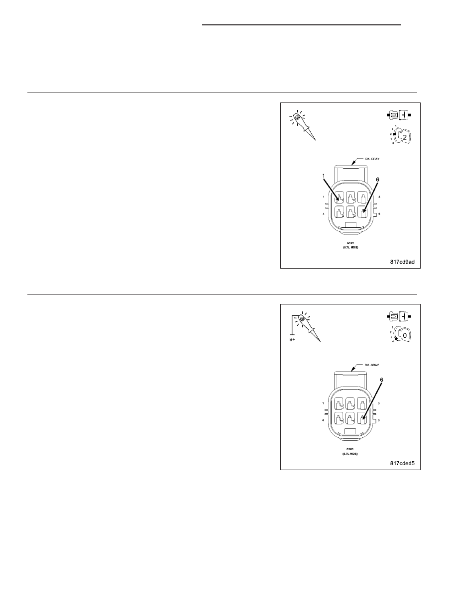
CHECKING PCM CONTROL SIDE FOR THE MDS SOLENOID BETWEEN C100 and C101
Turn the ignition off.
Reconnect the C100 harness connector.
Disconnect the C101 harness connector.
Using a 12-volt test light, jumper from the (Z904) Ground Circuit and the
(K451) MDS Solenoid No.1 Control Circuit in the C101 harness connec-
tor (PCM side).
Turn the ignition on.
With the scan tool, actuate the MDS Solenoid No.1.
Does the 12-volt test light flash on and off?
Yes
>> Visually and Physically inspect the wiring harness between
the C101 connector and the MDS Solenoid connector.
Repair as necessary. If OK, replace the MDS Solenoid in
accordance with the Service Information.
Perform the POWERTRAIN VERIFICATION TEST. (Refer to
9 - ENGINE - STANDARD PROCEDURE)
No
>> Go To 5
5.
(Z904) GROUND CIRCUIT OPEN BETWEEN C100 and C101
Turn the ignition off.
Using a 12-volt test light connected to the 12-volts, probe the (Z904)
Ground circuit in the C101 harness connector (PCM side).
Does the test light illuminate brightly?
Yes
>> Repair the (K451) MDS Solenoid No.1 Control circuit
between C100 and C101 connectors.
Perform the POWERTRAIN VERIFICATION TEST. (Refer to
9 - ENGINE - STANDARD PROCEDURE)
No
>> Repair the (Z904) Ground circuit between C100 and C101
connectors.
Perform the POWERTRAIN VERIFICATION TEST. (Refer to
9 - ENGINE - STANDARD PROCEDURE)
9 - 920
ENGINE ELECTRICAL DIAGNOSTICS
LX