Content .. 1220 1221 1222 1223 ..
Chrysler 300/300 Touring/300C, Dodge Magnum. Manual - part 1222
3.
EXCESSIVE RESISTANCE IN THE CASE GROUND
WARNING: When the engine is operating, do not stand in direct line with the fan. Do not put your hands
near the pulleys, belts, or fan. Do not wear loose clothing. Failure to follow these instructions can result in
personal injury or death.
Start the engine.
Warm the engine to operating temperature.
NOTE: Make sure all wires are clear of the engine’s moving parts.
Measure the voltage between the Generator Case and Battery ground post.
Is the voltage above 0.1 of a volt?
Yes
>> Repair the excessive resistance in the Generator Case Ground.
Perform the POWERTRAIN VERIFICATION TEST. (Refer to 9 - ENGINE - STANDARD PROCEDURE)
No
>> Go To 4
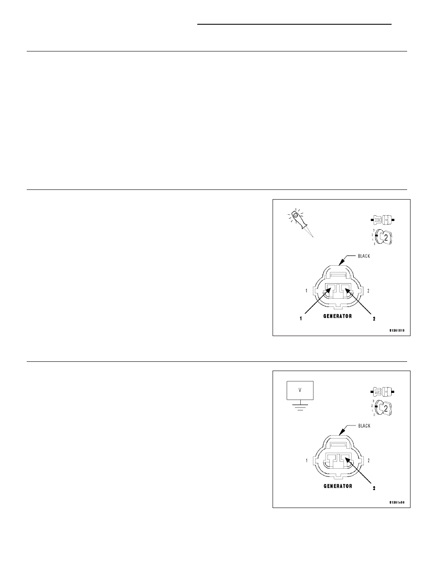
4.
GENERATOR OPERATION
Turn the ignition off.
Disconnect the Generator Field harness connector.
Using a 12-volt test light, jump across the Generator Field harness con-
nector.
Ignition on, engine not running.
With a scan tool, actuate the Generator Field Driver.
Does the test light illuminate brightly and flash on and off?
Yes
>> Replace the Generator.
Perform the POWERTRAIN VERIFICATION TEST. (Refer
to 9 - ENGINE - STANDARD PROCEDURE)
No
>> Go To 5
5.
(K20) GEN FIELD CONTROL CIRCUIT SHORTED TO BATTERY VOLTAGE
Turn the ignition off.
Disconnect the PCM harness connectors.
Ignition on, engine not running.
Measure the voltage on the (K20) Gen Field Control circuit in the Gen-
erator Field harness connector.
Is the voltage above 1.0 volt?
Yes
>> Repair the short to battery voltage in the (K20) Gen Field
Control circuit.
Perform the POWERTRAIN VERIFICATION TEST. (Refer
to 9 - ENGINE - STANDARD PROCEDURE)
No
>> Go To 6
9 - 912
ENGINE ELECTRICAL DIAGNOSTICS
LX