Chrysler 300/300 Touring/300C, Dodge Magnum. Manual - part 1221


  Index      Chrysler     Chrysler 300/300 Touring/300C, Dodge Magnum - service repair manual


Search            


Content   ..  1219  1220  1221  1222   ..


Chrysler 300/300 Touring/300C, Dodge Magnum. Manual - part 1221


6.

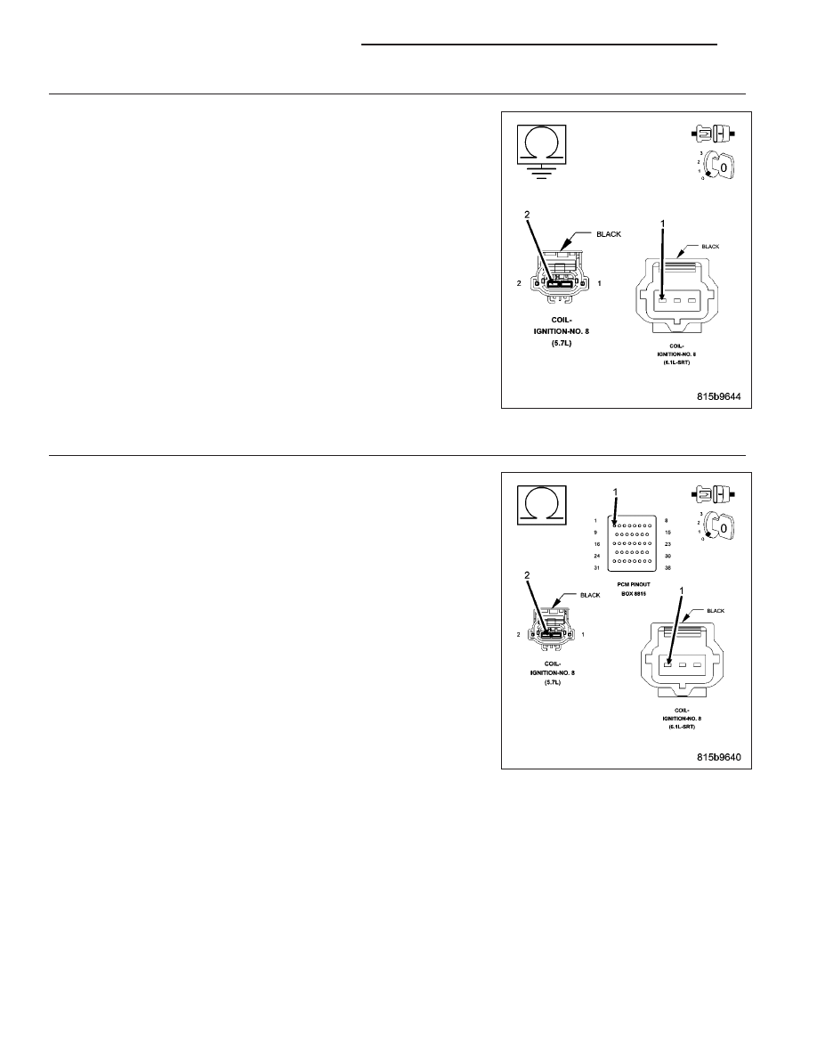
(K98) COIL CONTROL NO.8 CIRCUIT SHORTED TO GROUND

Turn the ignition off.

Disconnect the C2 PCM harness connector.

Measure the resistance between ground and the (K98) Coil Control
No.8 circuit in the Ignition Coil harness connector.

Is the resistance below 100 ohms?

Yes

>> Repair the short to ground in the (K98) Coil Control No.8

circuit.

Perform the POWERTRAIN VERIFICATION TEST. (Refer to
9 - ENGINE - STANDARD PROCEDURE)

No

>> Go To 8

7.

(K98) COIL CONTROL NO.8 CIRCUIT OPEN

Turn the ignition off.

Disconnect the C2 PCM harness connector.

CAUTION: Do not probe the PCM harness connectors. Probing the
PCM harness connectors will damage the PCM terminals resulting
in poor terminal to pin connection. Install Miller Special Tool #8815
to perform diagnosis.
Measure the resistance of the (K98) Coil Control No.8 circuit from the
Ignition Coil harness connector to the appropriate terminal of special
tool #8815.

Is the resistance below 5.0 ohms?

Yes

>> Go To 8

No

>> Repair the open in the (K98) Coil Control No.8 circuit.

Perform the POWERTRAIN VERIFICATION TEST. (Refer to
9 - ENGINE - STANDARD PROCEDURE)

9 - 908

ENGINE ELECTRICAL DIAGNOSTICS

LX

8.

PCM

NOTE: Before continuing, check the PCM harness connector terminals for corrosion, damage, or terminal
push out. Repair as necessary.
Using the schematics as a guide, inspect the wire harness and connectors. Pay particular attention to all Power and
Ground circuits.

Were there any problems found?

Yes

>> Repair as necessary.

Perform the POWERTRAIN VERIFICATION TEST. (Refer to 9 - ENGINE - STANDARD PROCEDURE)

No

>> Replace and program the Powertrain Control Module per Service Information.

Perform the POWERTRAIN VERIFICATION TEST. (Refer to 9 - ENGINE - STANDARD PROCEDURE)

9.

Visual and Physical Inspection

Turn the ignition off.

Remove the Spark Plug.

NOTE: Vehicles that are equipped with the 5.7L or 6.1L engines must have both spark plugs (per cylinder)
removed and inspected to ensure proper operation.
Inspect the Spark Plug for the following conditions.

− Cracks

− Carbon Tracking

− Foreign Material

− Gap size out of specifications

− Loose or broken electrode

NOTE: Lightly tap the bottom of the spark plug on a solid surface. The electrode in the spark plug should
not move.

Were any of the above conditions present?

Yes

>> Replace the Spark Plug.

Perform the POWERTRAIN VERIFICATION TEST. (Refer to 9 - ENGINE - STANDARD PROCEDURE)

No

>> Refer to the INTERMITTENT CONDITION symptom in the Driveability category.

LX

ENGINE ELECTRICAL DIAGNOSTICS

9 - 909

P2503-CHARGING SYSTEM OUTPUT LOW

For a complete wiring diagram Refer to Section 8W.

9 - 910

ENGINE ELECTRICAL DIAGNOSTICS

LX

When Monitored:
The engine running. The engine speed greater than 1157 RPM.

Set Condition:
The battery sensed voltage is 1 volt below the charging goal for 13.47 seconds. The PCM senses the battery
voltage turns off the field driver and senses the battery voltage again. If the voltages are the same, the code
is set. One Trip Fault. Three good trips to turn off the MIL.

Possible Causes

EXCESSIVE RESISTANCE IN THE BATTERY POSITIVE CIRCUIT

EXCESSIVE RESISTANCE IN THE CASE GROUND

(K20) GEN FIELD CONTROL CIRCUIT SHORTED TO VOLTAGE

(K20) GEN FIELD CONTROL CIRCUIT OPEN

(K20) GEN FIELD CONTROL CIRCUIT SHORTED TO GROUND

(Z904) GEN GROUND CIRCUIT OPEN

GENERATOR

PCM

Always perform the Pre-Diagnostic Troubleshooting procedure before proceeding. (Refer to 9 - ENGINE -
DIAGNOSIS AND TESTING).

Diagnostic Test

1.

ACTIVE DTC

NOTE: Inspect the vehicle for aftermarket accessories that may exceed the Generator System output.
Ignition on, engine not running.

NOTE: The battery must be fully charged.

NOTE: The Generator belt tension and condition must be checked before continuing.
With a scan tool, read DTCs.

With a scan tool, erase DTCs.

Start the engine.

Allow the idle to stabilize.

With the scan tool, read DTCs.

Is the DTC active at this time?

Yes

>> Go To 2

No

>> Refer to the INTERMITTENT CONDITION Diagnostic Procedure.

Perform the POWERTRAIN VERIFICATION TEST. (Refer to 9 - ENGINE - STANDARD PROCEDURE)

2.

FUSED B+ CIRCUIT HIGH RESISTANCE

WARNING: When the engine is operating, do not stand in direct line with the fan. Do not put your hands
near the pulleys, belts, or fan. Do not wear loose clothing. Failure to follow these instructions can result in
personal injury or death.
Ignition on, engine not running.

NOTE: Make sure all wires are clear of the engine’s moving parts.
Measure the voltage between the Generator B+ Output Terminal and the Battery+ Post.

Start the engine.

Is the voltage above 0.4 of a volt?

Yes

>> Repair the excessive resistance in the battery positive circuit between the Generator and Battery.

Perform the POWERTRAIN VERIFICATION TEST. (Refer to 9 - ENGINE - STANDARD PROCEDURE)

No

>> Go To 3

LX

ENGINE ELECTRICAL DIAGNOSTICS

9 - 911


Content   ..  1219  1220  1221  1222   ..