Chrysler 300/300 Touring/300C, Dodge Magnum. Manual - part 1219


  Index      Chrysler     Chrysler 300/300 Touring/300C, Dodge Magnum - service repair manual


Search            


Content   ..  1217  1218  1219  1220   ..


Chrysler 300/300 Touring/300C, Dodge Magnum. Manual - part 1219


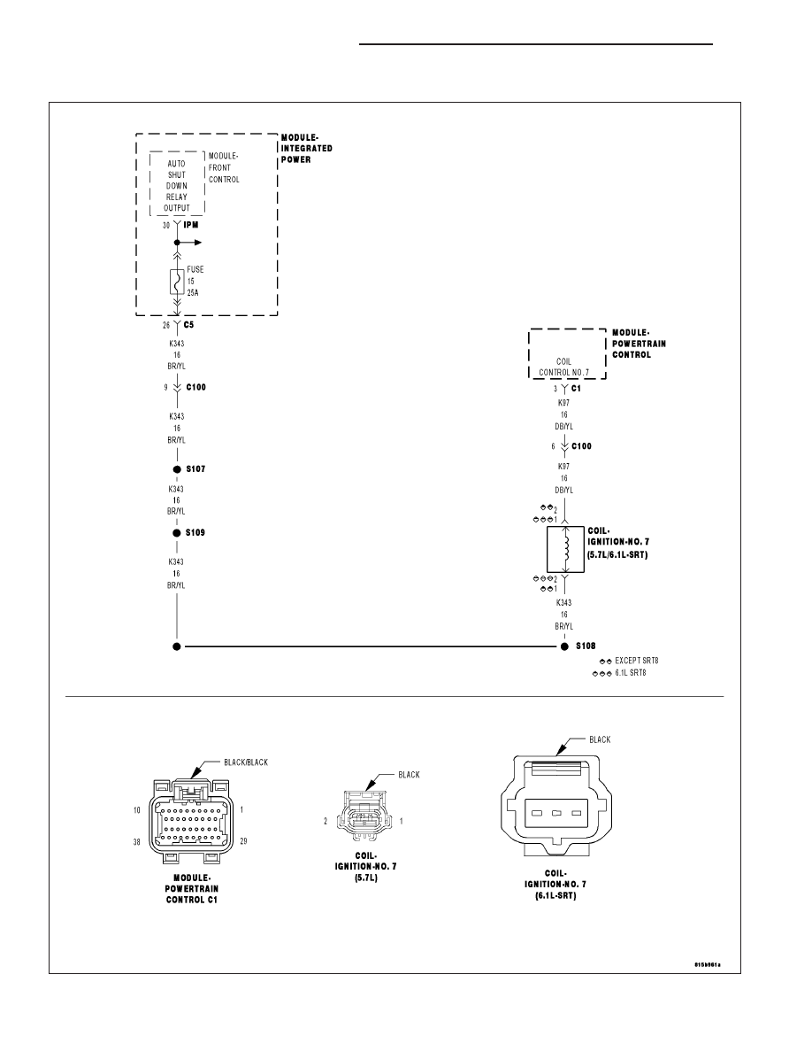
P2320-IGNITION COIL 7 SECONDARY CIRCUIT- INSUFFICIENT IONIZATION

For a complete wiring diagram Refer to Section 8W.

9 - 900

ENGINE ELECTRICAL DIAGNOSTICS

LX

When Monitored:
Engine running and battery voltage greater than 10 volts.

Set Condition:
If PCM detects that the secondary ignition burn time is incorrect, too short, or not present, an error is detected.
One Trip Fault. Three good trips to turn off the MIL.

Possible Causes

(K343) ASD RELAY OUTPUT 2 CIRCUIT

(K97) COIL CONTROL NO.7 CIRCUIT OPEN

(K97) COIL CONTROL NO.7 CIRCUIT SHORTED TO GROUND

SPARK PLUG

COIL ON PLUG

PCM

Always perform the Pre-Diagnostic Troubleshooting procedure before proceeding. (Refer to 9 - ENGINE -
DIAGNOSIS AND TESTING).

Diagnostic Test

1.

ACTIVE DTC

Ignition on, engine not running.

With a scan tool, read DTCs.

Is the DTC active at this time?

Yes

>> Go To 2

No

>> Go To 9

Perform the POWERTRAIN VERIFICATION TEST. (Refer to 9 - ENGINE - STANDARD PROCEDURE)

2.

Secondary Spark

NOTE: Inspect the ignition coil for damage, carbon tracking on the coil or a damaged spark plug insulator
boot. If a problem is found, replace the ignition coil.
Turn the ignition off.

Remove the ignition coil.

NOTE: 6.1L coils must have a spark tester installed on both sides of the coil during the following test. Dur-
ing the test, each side of the coil should output a crisp blue spark that is able to jump the gap of the spark
tester.
Install a spark tester(s) to the ignition coil.

While cranking the engine observe the spark coming from the spark tester.

NOTE: A crisp blue spark that is able to jump the gap of the spark tester should be generated.

Is good spark generated?

Yes

>> Ensure the cylinder is operating properly. If OK, replace the Spark Plug.

Perform the POWERTRAIN VERIFICATION TEST. (Refer to 9 - ENGINE - STANDARD PROCEDURE)

No

>> Go To 3

LX

ENGINE ELECTRICAL DIAGNOSTICS

9 - 901

3.

(K343) ASD RELAY OUTPUT2 CIRCUIT

Turn the ignition off.

Disconnect the Ignition Coil harness connector.

Ignition on, engine not running.

With a scan tool, actuate the ASD Relay.

Using a 12-volt test light connected to ground, probe the (K343) ASD
Relay Output 2 circuit in the Coil on Plug harness connector.

Does the test light illuminate brightly?

Yes

>> Go To 4

No

>> Repair the open or short to ground in the (K343) ASD Relay

Output 2 circuit between the IPM and Coil harness connec-
tor.

Perform the POWERTRAIN VERIFICATION TEST. (Refer to
9 - ENGINE - STANDARD PROCEDURE)

4.

IGNITION COIL RESISTANCE

Turn the ignition off.

NOTE: The following resistance measurement should be taken at 70°-80° F.
Measure the resistance of the Ignition Coil.

Is the resistance between 0.53 to 0.65 ohms at 77°F (25°C) for the Ignition Coil being tested?

Yes

>> Go To 5

No

>> Replace the Ignition Coil.

Perform the POWERTRAIN VERIFICATION TEST. (Refer to 9 - ENGINE - STANDARD PROCEDURE)

5.

IGNITION COIL

Using a 12-volt test light connected to a 12-volt source, probe the (K97)
Coil Control No.7 circuit.

Crank the engine for 5 seconds while observing the test light.

What is the condition of the test light while cranking the
engine?

Brightly blinking.

Replace the Ignition Coil.

Perform the POWERTRAIN VERIFICATION TEST. (Refer to
9 - ENGINE - STANDARD PROCEDURE)

ON constantly.

Go To 6

OFF constantly.

Go To 7

9 - 902

ENGINE ELECTRICAL DIAGNOSTICS

LX

6.

(K97) COIL CONTROL NO.7 CIRCUIT SHORTED TO GROUND

Turn the ignition off.

Disconnect the C2 PCM harness connector.

Measure the resistance between ground and the (K97) Coil Control
No.7 circuit in the Ignition Coil harness connector.

Is the resistance below 100 ohms?

Yes

>> Repair the short to ground in the (K97) Coil Control No.7

circuit.

Perform the POWERTRAIN VERIFICATION TEST. (Refer to
9 - ENGINE - STANDARD PROCEDURE)

No

>> Go To 8

7.

(K97) COIL CONTROL NO.7 CIRCUIT OPEN

Turn the ignition off.

Disconnect the C2 PCM harness connector.

CAUTION: Do not probe the PCM harness connectors. Probing the
PCM harness connectors will damage the PCM terminals resulting
in poor terminal to pin connection. Install Miller Special Tool #8815
to perform diagnosis.
Measure the resistance of the (K97) Coil Control No.7 circuit from the
Ignition Coil harness connector to the appropriate terminal of special
tool #8815.

Is the resistance below 5.0 ohms?

Yes

>> Go To 8

No

>> Repair the open in the (K97) Coil Control No.7 circuit.

Perform the POWERTRAIN VERIFICATION TEST. (Refer to
9 - ENGINE - STANDARD PROCEDURE)

LX

ENGINE ELECTRICAL DIAGNOSTICS

9 - 903


Content   ..  1217  1218  1219  1220   ..