Chrysler 300/300 Touring/300C, Dodge Magnum. Manual - part 1186


  Index      Chrysler     Chrysler 300/300 Touring/300C, Dodge Magnum - service repair manual


Search            


Content   ..  1184  1185  1186  1187   ..


Chrysler 300/300 Touring/300C, Dodge Magnum. Manual - part 1186


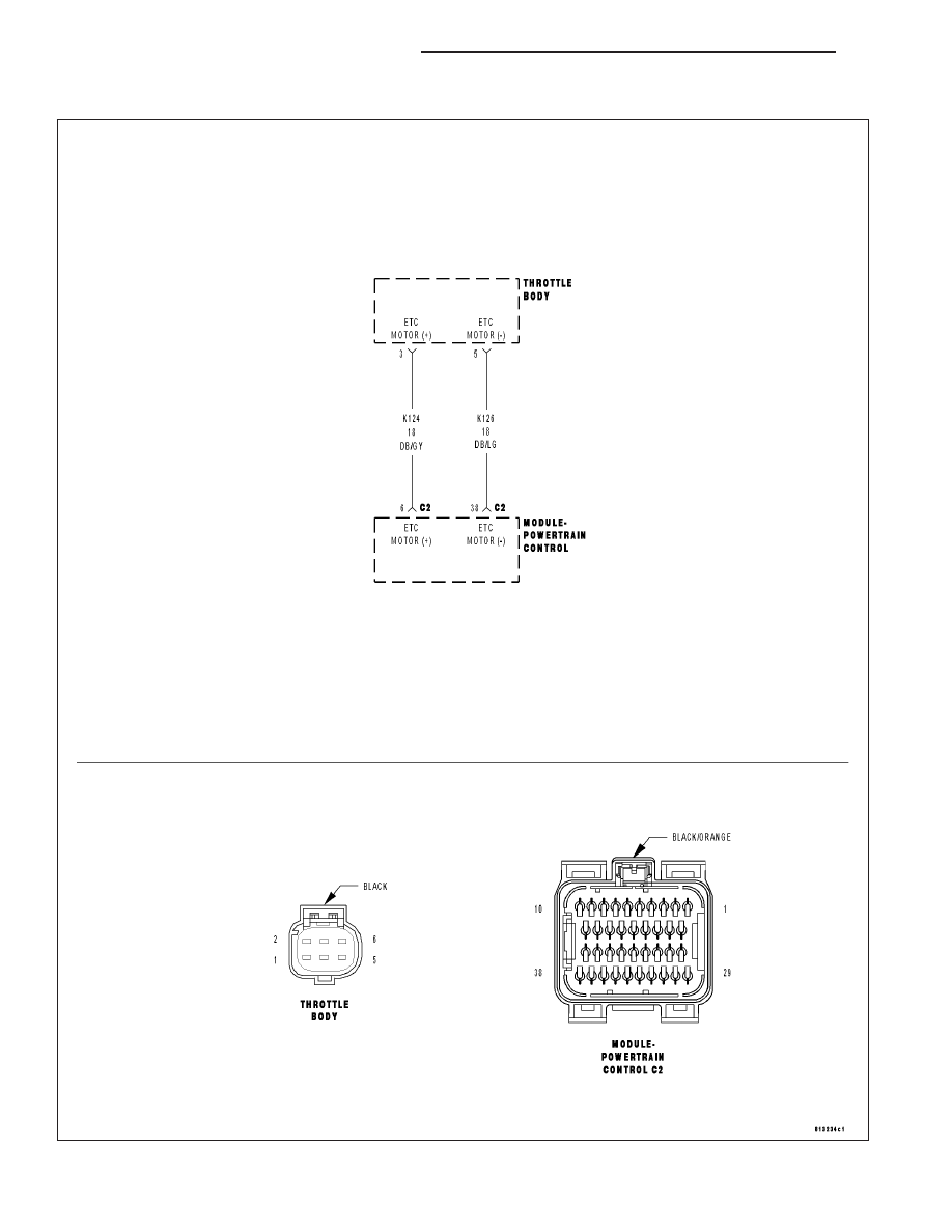
P2118-ELECTRONIC THROTTLE CONTROL MOTOR CIRCUIT

For a complete wiring diagram Refer to Section 8W.

9 - 768

ENGINE ELECTRICAL DIAGNOSTICS

LX

When Monitored:
With the ignition on and the ETC Motor is not in Limp Home mode.

Set Condition:
When the PCM detects an internal error or a short between the ETC Motor- and ETC Motor + circuits in the
ETC Motor Driver. One trip fault. ETC light is flashing.

Possible Causes

THROTTLE PLATE / BORE INSPECTION

(K124) ETC POSITIVE CIRCUIT SHORTED TO BATTERY VOLTAGE

(K126) ETC NEGATIVE CIRCUIT SHORTED TO BATTERY VOLTAGE

(K124) ETC POSITIVE CIRCUIT SHORTED TO (K126) ETC NEGATIVE CIRCUIT

(K124) ETC POSITIVE CIRCUIT OPEN

(K124) ETC POSITIVE CIRCUIT SHORTED TO GROUND

(K126) ETC NEGATIVE CIRCUIT OPEN

(K126) ETC NEGATIVE CIRCUIT SHORTED TO GROUND

ETC MOTOR

PCM

Always perform the Pre-Diagnostic Troubleshooting procedure before proceeding. (Refer to 9 - ENGINE -
DIAGNOSIS AND TESTING).

Diagnostic Test

1.

ACTIVE DTC

Ignition on, engine not running.

NOTE: If the P2118 is intermittent, it is possible that the controller is overheating in extreme hot tempera-
tures, and this is considered a normal protection operation. No repair is necessary.
With a scan tool, read DTCs.

Look closely at the temperatures at which this DTC set.

Is the DTC active at this time?

Yes

>> Go To 2

No

>> Refer to the INTERMITTENT CONDITION Diagnostic Procedure.

Perform the POWERTRAIN VERIFICATION TEST. (Refer to 9 - ENGINE - STANDARD PROCEDURE)

2.

THROTTLE PLATE INSPECTION

Turn the ignition off.

Remove the Air Cleaner Assembly from the Throttle Body.

Check for any signs of a foreign material (ice or dirt) on the Throttle Plate or in the bore causing the Throttle Plate
to stick.

Were any signs of foreign material or scoring of the throttle plate or bore found?

Yes

>> Remove the debris if possible or replace the Throttle Body Assembly. Disconnect the Battery when

replacing the Throttle Body Assembly. After installation is complete, use a scan tool and select the ETC
RELEARN function.

Perform the POWERTRAIN VERIFICATION TEST. (Refer to 9 - ENGINE - STANDARD PROCEDURE)

No

>> Go To 3

LX

ENGINE ELECTRICAL DIAGNOSTICS

9 - 769

3.

(K124) ETC POSITIVE CIRCUIT SHORTED TO BATTERY VOLTAGE

Turn the ignition off.

Disconnect the Throttle Body harness connector.

Disconnect the C3/C PCM harness connector.

Ignition on, engine not running.

CAUTION: Do not probe the PCM harness connectors. Probing the
PCM harness connectors will damage the PCM terminals resulting
in poor terminal to pin connection. Install Miller Special Tool #8815
to perform diagnosis.
With a 12-volt test light connected to ground, probe the (K124) ETC
Positive circuit at the appropriate terminal of the special tool #8815.

Does the test light illuminate brightly?

Yes

>> Repair the short to battery voltage on the (K124) ETC Pos-

itive circuit.

Perform the POWERTRAIN VERIFICATION TEST. (Refer
to 9 - ENGINE - STANDARD PROCEDURE)

No

>> Go To 4

4.

(K126) ETC NEGATIVE CIRCUIT SHORTED TO BATTERY VOLTAGE

Using a 12-volt test light connected to ground, probe the (K126) ETC
Negative circuit at the appropriate terminal of the special tool #8815.

Does the test light illuminate brightly?

Yes

>> Repair the short to battery voltage in the (K126) ETC Neg-

ative circuit.

Perform the POWERTRAIN VERIFICATION TEST. (Refer
to 9 - ENGINE - STANDARD PROCEDURE)

No

>> Go To 5

9 - 770

ENGINE ELECTRICAL DIAGNOSTICS

LX

5.

(K124) ETC POSITIVE CIRCUIT SHORTED TO THE (K126) ETC NEGATIVE CIRCUIT

Measure the resistance between the (K124) ETC Positive circuit and
the (K126) ETC Negative circuit at the appropriate terminal of the spe-
cial tool #8815.

Is the resistance below 100 ohms?

Yes

>> Repair the short to between the (K124) ETC Positive circuit

and the (K126) ETC Negative circuit.

Perform the POWERTRAIN VERIFICATION TEST. (Refer
to 9 - ENGINE - STANDARD PROCEDURE)

No

>> Go To 6

6.

(K124) ETC POSITIVE CIRCUIT OPEN

Turn the ignition off.

Measure the resistance of the (K124) ETC Positive circuit from the
Throttle Body harness connector to the appropriate terminal of special
tool #8815.

Is the resistance below 5.0 ohms?

Yes

>> Go To 7

No

>> Repair the open in the (K124) ETC Positive circuit.

Perform the POWERTRAIN VERIFICATION TEST. (Refer
to 9 - ENGINE - STANDARD PROCEDURE)

LX

ENGINE ELECTRICAL DIAGNOSTICS

9 - 771


Content   ..  1184  1185  1186  1187   ..