Content .. 1185 1186 1187 1188 ..
Chrysler 300/300 Touring/300C, Dodge Magnum. Manual - part 1187
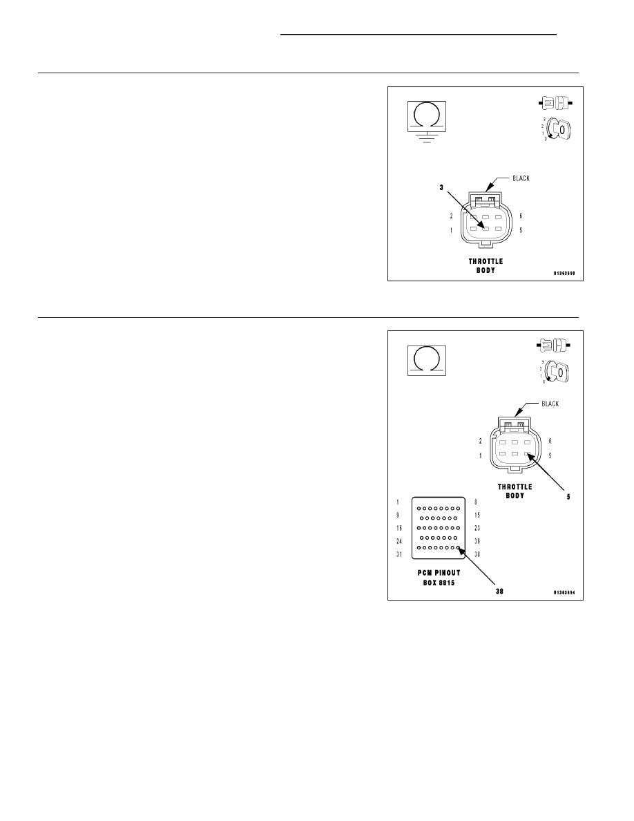
7.
(K124) ETC POSITIVE CIRCUIT SHORTED TO GROUND
Measure the resistance between ground and the (K124) ETC Positive
circuit at the appropriate terminal of the special tool #8815.
Is the resistance below 100 ohms?
Yes
>> Repair the short to ground in the (K124) ETC Positive cir-
cuit.
Perform the POWERTRAIN VERIFICATION TEST. (Refer
to 9 - ENGINE - STANDARD PROCEDURE)
No
>> Go To 8
8.
(K126) ETC NEGATIVE CIRCUIT OPEN
Measure the resistance of the (K126) ETC Negative circuit between the
Throttle Body harness connector and the appropriate terminal of special
tool #8815.
Is the resistance below 5.0 ohms?
Yes
>> Go To 9
No
>> Repair the open in the (K126) ETC Negative circuit.
Perform the POWERTRAIN VERIFICATION TEST. (Refer
to 9 - ENGINE - STANDARD PROCEDURE)
9 - 772
ENGINE ELECTRICAL DIAGNOSTICS
LX