Content .. 1003 1004 1005 1006 ..
Chrysler 300/300 Touring/300C, Dodge Magnum. Manual - part 1005
3.
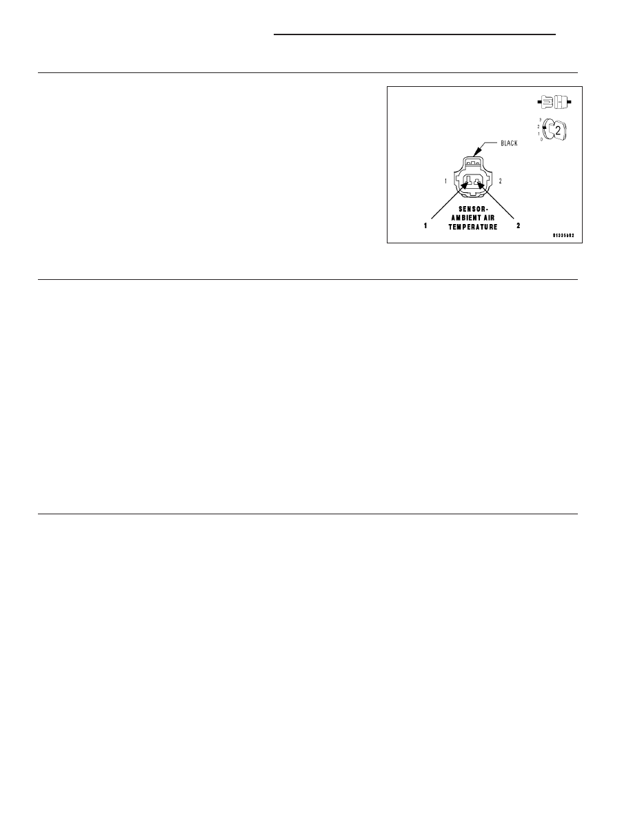
AAT SENSOR
Connect a jumper wire between the (G31) AAT Signal circuit and the
(G931) Sensor ground circuit in the AAT Sensor harness connector.
With a scan tool, read the AAT voltage.
Is the voltage below 1.0 volt with the jumper wire installed?
Yes
>> Replace the AAT Sensor.
Perform the POWERTRAIN VERIFICATION TEST. (Refer
to 9 - ENGINE - STANDARD PROCEDURE)
No
>> Go To 4
NOTE: Remove the jumper wire before continuing.
4.
(G31) AAT SIGNAL CIRCUIT HIGH RESISTANCE
Turn the ignition off.
Reconnect the AAT sensor harness connector.
Using a voltmeter perform a voltage drop test. Backprobe the (G31) AAT Signal circuit at the AAT sensor harness
connector and the FCM.
WARNING: WARNING: When the engine is operating, do not stand in direct line with the fan. Do not put
your hands near the pulleys, belts, or fan. Do not wear loose clothing. Failure to follow these instructions
can result in personal injury or death.
Start the engine and allow it to reach normal operating temperature.
Monitor the voltmeter.
Is the voltage below 0.5 volts?
Yes
>> Go To 5
No
>> Repair the high resistance in the (G31) AAT Signal circuit.
Perform the POWERTRAIN VERIFICATION TEST. (Refer to 9 - ENGINE - STANDARD PROCEDURE)
5.
(G931) SENSOR GROUND CIRCUIT HIGH RESISTANCE
Turn the ignition off.
Reconnect the AAT sensor harness connector.
Using a voltmeter perform a voltage drop test. Backprobe the (G931) Sensor ground circuit at the AAT sensor har-
ness connector and the FCM.
WARNING: When the engine is operating, do not stand in direct line with the fan. Do not put your hands near the
pulleys, belts, or fan. Do not wear loose clothing. Failure to follow these instructions can result in personal injury or
death.
Start the engine and allow it to reach normal operating temperature.
Monitor the voltmeter.
Is the voltage below 0.5 volts?
Yes
>> Go To 6
No
>> Repair the high resistance in the (G931) Sensor ground circuit.
Perform the POWERTRAIN VERIFICATION TEST. (Refer to 9 - ENGINE - STANDARD PROCEDURE)
9 - 44
ENGINE ELECTRICAL DIAGNOSTICS
LX