Chrysler 300/300 Touring/300C, Dodge Magnum. Manual - part 76


  Index      Chrysler     Chrysler 300/300 Touring/300C, Dodge Magnum - service repair manual


Search            


Content   ..  74  75  76  77   ..


Chrysler 300/300 Touring/300C, Dodge Magnum. Manual - part 76


CAUTION: When venting the inner tripod joint assembly, use care so inner tripod sealing boot does not get
punctured, or in any other way damaged. If sealing boot is punctured, or damaged in any way while being
vented, the sealing boot can not be used.

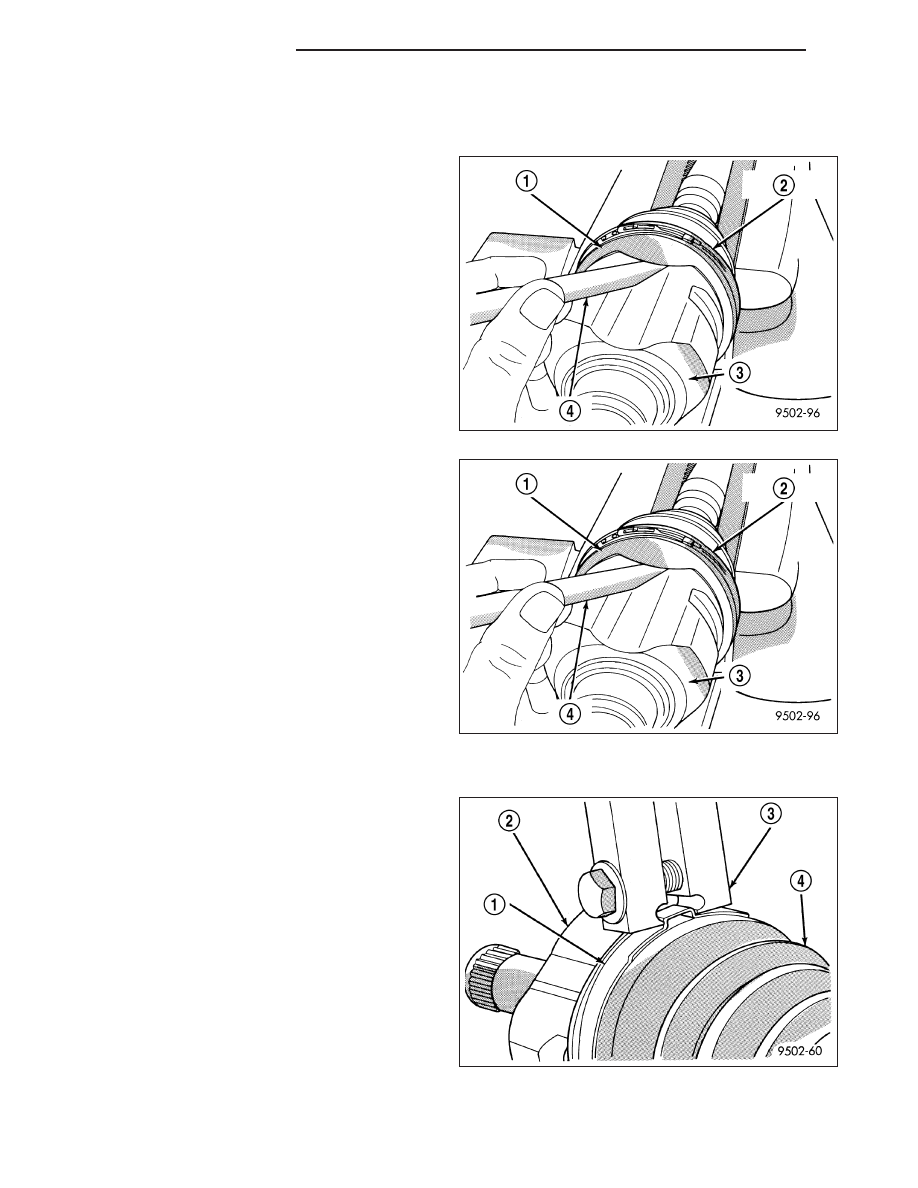
10. Insert a trim stick (4) between the tripod joint (3)

and the sealing boot (2) to vent inner tripod joint
assembly. When inserting trim stick between
tripod housing and sealing boot ensure trim
stick is held flat and firmly against the tripod
housing. If this is not done damage to the
sealing boot can occur. 
If inner tripod joint has a
Hytrel (hard plastic) sealing boot, be sure trim
stick is inserted between soft rubber insert and tri-
pod housing not the hard plastic sealing boot and
soft rubber insert.

11. With trim stick inserted between sealing boot and

tripod joint housing, position the interconnecting
shaft so it is at the center of its travel in the tripod
joint housing. Remove the trim stick from between
the sealing boot and the tripod joint housing. This
procedure will equalize the air pressure in the
tripod joint, preventing premature sealing boot
failure.

12. Position trilobal boot to interface with the tripod

housing. The lobes of the boot must be properly
aligned with the recess’s of the tripod housing.

13. Clamp tripod joint sealing boot to tripod joint,

using required procedure for type of boot clamp
application.

CRIMP TYPE BOOT CLAMP

1. Clamp sealing boot onto tripod housing using

Crimper, Special Tool C-4975-A (3).

2. Place crimping tool C-4975-A over bridge of clamp.

3 - 36

SHAFT-HALF (FRONT)

LX

3. Tighten nut on crimping tool C-4975-A (3) until jaws

on tool are closed completely together, face to face
(4).

LATCHING TYPE BOOT CLAMP

1. Clamp sealing boot (3) onto tripod housing using

clamp locking tool, Snap-On YA3050 (2) or an
equivalent.

2. Place prongs of clamp locking tool in the holes of

the clamp (1).

3. Squeeze tool together until top band of clamp is

latched behind the two tabs on lower band of
clamp (2).

LX

SHAFT-HALF (FRONT)

3 - 37

BOOT-CV OUTER

REMOVAL

1. Remove large boot clamp (4) retaining C/V joint

sealing boot to C/V joint housing and discard.
Remove small clamp (1) that retains outer C/V joint
sealing boot to interconnecting shaft and discard.
Remove sealing boot from outer C/V joint housing
and slide it down interconnecting shaft.

2. Wipe away grease to expose outer C/V joint and

interconnecting shaft.

3. Remove outer C/V joint from interconnecting shaft

using the following procedure: Support intercon-
necting shaft in a vise equipped with protective
caps on jaws of vise to prevent damage to
interconnecting shaft. 
Then, using a soft–faced
hammer, 
sharply hit the end of the C/V joint hous-
ing to dislodge housing from internal circlip on
interconnecting shaft. Then slide outer C/V joint off
end of interconnecting shaft, joint may have to be
tapped off shaft using a soft–faced hammer.

4. Remove large circlip from the interconnecting shaft

(3) before attempting to remove outer C/V joint
sealing boot.

5. Slide failed sealing boot off interconnecting shaft.

6. Thoroughly clean and inspect outer C/V joint

assembly and interconnecting joint for any signs of
excessive wear. If any parts show signs of
excessive wear, the driveshaft assembly will
require replacement. Component parts of these
driveshaft assemblies are not serviceable.

3 - 38

SHAFT-HALF (FRONT)

LX

INSTALLATION

1. Slide new sealing boot (1) to interconnecting shaft

retaining clamp onto interconnecting shaft. Slide
the outer C/V joint assembly sealing boot onto the
interconnecting shaft. Seal boot MUST be posi-
tioned on interconnecting shaft so the raised
bead on the inside of the seal boot is in groove
on interconnecting shaft.

2. Align splines on interconnecting shaft with splines

on cross of outer C/V joint assembly and start
outer C/V joint onto interconnecting shaft.

3. Install outer C/V joint assembly onto interconnect-

ing shaft by using a soft–faced hammer (1) and
tapping end of stub axle (with nut installed) until
outer C/V joint is fully seated on interconnecting
shaft.

4. Outer C/V joint assembly must be installed on

interconnecting shaft until cross of outer C/V joint
assembly is seated against circlip on interconnect-
ing shaft (1).

LX

SHAFT-HALF (FRONT)

3 - 39


Content   ..  74  75  76  77   ..