Chrysler 300/300 Touring/300C, Dodge Magnum. Manual - part 39
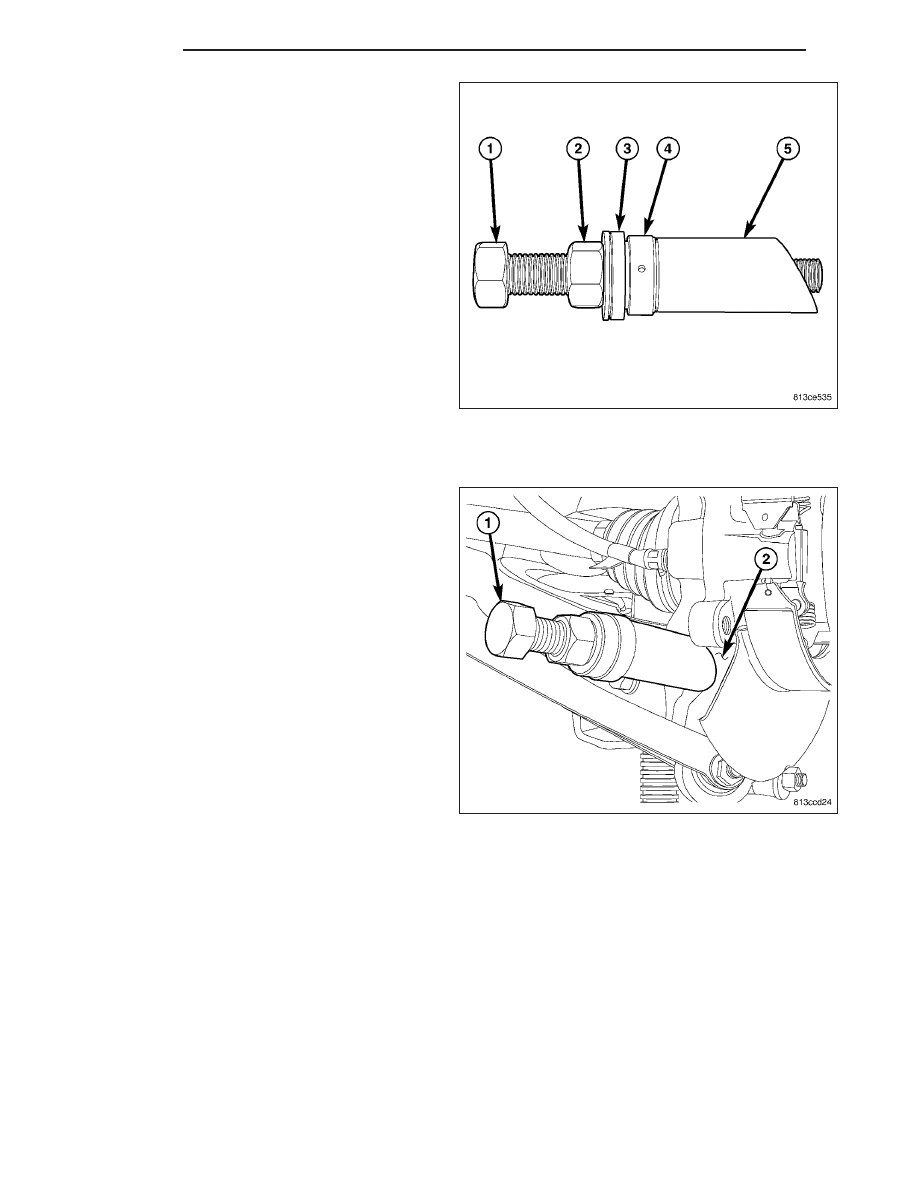
NOTE: Prior to using Special Tool 9361, lubricate
Bolt (1) threads to provide ease of use and pro-
mote tool longevity.
13. Assemble Remover, Special Tool 9361, as shown.
•
(1) Bolt 9361-3
•
(2) Nut
•
(3) Spherical Washer
•
(4) Thrust Bearing
•
(5) Sleeve 9361-4 (RWD)
•
(5) Sleeve 9361-5 (AWD – Left Side)
•
(5) Sleeve 9361-6 (AWD – Right Side)
NOTE: When installing thrust bearing on Remover,
be sure to place hardened side against nut. Place
bearing outer cage against stationary component.
NOTE: It is important to use appropriate Sleeve on
Remover to provide proper Tool-to-Knuckle contact. RWD sleeve can be used on either side while AWD
knuckles require specific left or right side Sleeves.
14. Thread Remover Bolt 9361-3 (1) into tapped
knuckle sleeve.
15. Rotate Nut down, matching Sleeve angled end
with angled face of knuckle.
16. Continue to rotate Nut until knuckle sleeve is
removed from knuckle. Discard knuckle sleeve;
replace it with new upon installation.
2 - 110
REAR
LX