Chrysler 300/300 Touring/300C, Dodge Magnum. Manual - part 33


  Index      Chrysler     Chrysler 300/300 Touring/300C, Dodge Magnum - service repair manual


Search            


Content   ..  31  32  33  34   ..


Chrysler 300/300 Touring/300C, Dodge Magnum. Manual - part 33


CAUTION: In following step, use care not to dam-
age ball joint seal boot while sliding Puller, Special
Tool 9360, into place past seal boot.

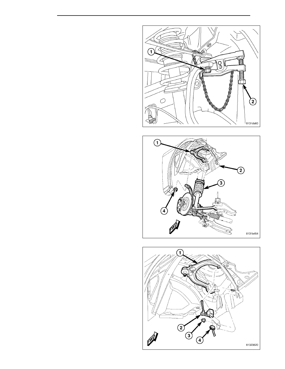
10. Using Puller (2), Special Tool 9360, separate

upper ball joint stud (1) from knuckle.

11. Remove nut (4) from end of upper ball joint stud

(1).

12. Pull shock assembly (3) downward until studs

clear shock tower (2), then pull it outward allowing
access to upper control arm mounting bolts.

13. Export Only – If servicing right upper control arm,

disconnect headlamp leveling sensor (2) link at
upper control arm (1).

2 - 86

FRONT

LX

14. Remove upper control arm mounting (flag) bolts

(1).

15. Remove upper control arm (2) from bracket (3) in

shock tower (4).

INSTALLATION

NOTE: Although AWD and RWD upper control arms are similar in appearance, they are not interchangeable.

1. Slide upper control arm (2) into bracket (3) located

in shock tower (4).

2. Install upper control arm mounting (flag) bolts (1)

through bracket, arm and tower. Position flags on
bolt heads outward, toward wheel opening.

LX

FRONT

2 - 87

3. Export Only – If servicing right upper control arm,

connect headlamp leveling sensor (2) link at upper
control arm (1).

4. Move shock assembly (3) allowing studs to be

inserted through shock tower (2) mounting holes.

5. Place upper ball joint stud (1) through hole in top of

knuckle and install nut (4). Tighten nut by holding
ball joint stud with a hex wrench while turning nut
with a wrench. Tighten nut using crow foot wrench
on torque wrench to 47 N·m + 90° turn (35 ft. lbs. +
90° turn) torque.

6. Connect wheel speed sensor cable routing clip (2)

at brake tube bracket (3).

2 - 88

FRONT

LX

7. Install tire and wheel assembly (1) (Refer to 22 -

TIRES/WHEELS - INSTALLATION). Tighten wheel
mounting nuts (3) to 150 N·m (110 ft. lbs.) torque.

8. Lower vehicle to curb position.

9. Install nuts (2) on upper control arm body mounting

bolts (1). Tighten nuts to 75 N·m (55 ft. lbs.) torque.

10. Install three nuts (2) fastening shock assembly (4)

to shock tower (3). Tighten nuts to 27 N·m (20 ft.
lbs.) torque.

11. If equipped, align shock tower cap (1) with shock

mounting nuts (2) and snap into place.

LX

FRONT

2 - 89


Content   ..  31  32  33  34   ..