Chrysler 300/300 Touring/300C, Dodge Magnum. Manual - part 31


  Index      Chrysler     Chrysler 300/300 Touring/300C, Dodge Magnum - service repair manual


Search            


Content   ..  29  30  31  32   ..


Chrysler 300/300 Touring/300C, Dodge Magnum. Manual - part 31


STRUT - TENSION

REMOVAL

1. Raise and support vehicle. (Refer to LUBRICATION & MAINTENANCE/HOISTING - STANDARD PROCEDURE)

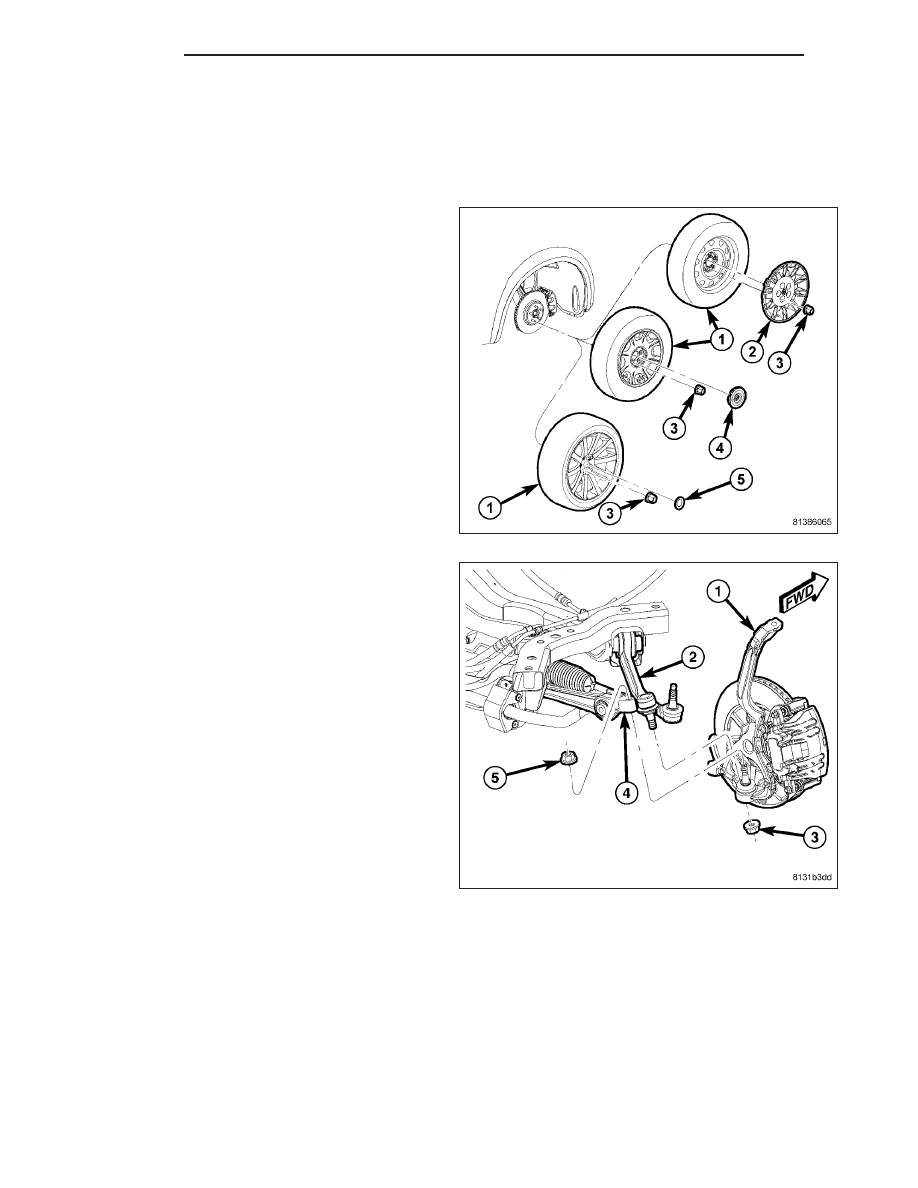
2. Remove wheel mounting nuts (3), then tire and

wheel assembly (1).

3. Remove belly pan. (Refer to 23 - BODY/EXTERI-

OR/BELLY PAN - REMOVAL)

4. Loosen nut (3) attaching tension strut (2) ball joint

stud to knuckle. Back nut off until nut is even with
end of stud. Keeping nut on at this location will
help keep end of stud from distorting while
using Puller in next step.

2 - 78

FRONT

LX

CAUTION: In following step, use care not to dam-
age ball joint seal boot while sliding Puller, Special
Tool 9360, into place past seal boot.

5. Using Puller (1), Special Tool 9360, separate ten-

sion strut ball joint stud (2) from knuckle.

6. Remove nut (3) from end of tension strut (2) ball

joint stud.

7. Rotate knuckle outward and push ball joint upward,

out of knuckle.

CAUTION: If the tension strut bolt at the engine
cradle has a lengthwise grooved shaft (2), it is a
special wheel alignment adjustment bolt and the
bolt head (1) must not be rotated in the vehicle or
damage to the bolt and engine cradle will result.
While holding the bolt in place with a wrench,
remove the nut, then slide the bolt out of the
bushing and cradle taking note of bolt positioning
in engine cradle for reassembly purposes. The
bolt needs to be installed in the same position as
removed to make sure wheel camber and caster
return to adjusted position.

LX

FRONT

2 - 79

8. Remove nut and bolt (2) securing tension strut (1)

to engine cradle (3).

9. Slide tension strut out of cradle bracket and

remove from vehicle.

INSTALLATION

NOTE: If installing a tension strut engine cradle
bolt that is a wheel alignment adjustment bolt
(lengthwise grooved shaft (2)), make sure to install
it in the same position which it was in upon
removal. For more details on installation of this
special bolt, (Refer to 2 - SUSPENSION/WHEEL
ALIGNMENT - STANDARD PROCEDURE).

1. Slide bushing end of tension strut (1) into cradle

bracket (3).

2. Install mounting bolt (2) from front through cradle

and bushing.

3. Install nut (2), but do not tighten at this time.

2 - 80

FRONT

LX

4. Insert tension strut (2) ball joint stud downward,

into knuckle hole.

5. Completely install NEW nut (3) on ball joint stud

attaching tension strut (2) to knuckle (1). Tighten
nut by holding ball joint stud with a hex wrench
while turning nut with a wrench. Tighten nut using
crow foot wrench on torque wrench to 68 N·m +
90° turn (50 ft. lbs. + 90° turn) torque.

6. Install tire and wheel assembly (1) (Refer to 22 - TIRES/WHEELS - INSTALLATION). Tighten wheel mounting

nuts (3) to 150 N·m (110 ft. lbs.) torque.

7. Lower vehicle.

8. Position vehicle on an alignment rack/drive-on lift.

9. Perform wheel alignment. (Refer to 2 - SUSPEN-

SION/WHEEL ALIGNMENT - STANDARD PROCE-
DURE)

CAUTION: If the tension strut engine cradle bolt is
a wheel alignment adjustment bolt (lengthwise
grooved shaft (2)), be sure to only tighten the nut.
Do not rotate the bolt head (1) or damage to the
bushing will occur.

LX

FRONT

2 - 81


Content   ..  29  30  31  32   ..