Chrysler 300/300 Touring/300C, Dodge Magnum. Manual - part 18


  Index      Chrysler     Chrysler 300/300 Touring/300C, Dodge Magnum - service repair manual


Search            


Content   ..  16  17  18  19   ..


Chrysler 300/300 Touring/300C, Dodge Magnum. Manual - part 18


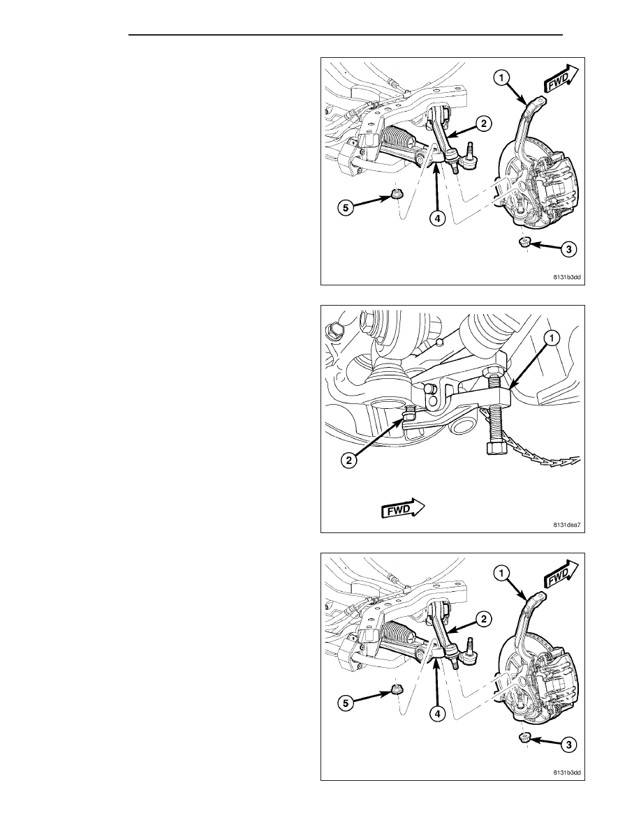
12. Loosen nut (3) attaching tension strut (2) ball joint

stud to knuckle. Back nut off until nut is even with
end of stud. Keeping nut on at this location will
help keep end of stud from distorting while
using Puller in next step.

CAUTION: In following step, use care not to dam-
age ball joint seal boot while sliding Puller, Special
Tool 9360, into place past seal boot.

13. Using Puller (1), Special Tool 9360, separate ten-

sion strut ball joint stud (2) from knuckle.

14. Remove nut (3) from end of tension strut (2) ball

joint stud.

15. Loosen nut (5) attaching ball joint stud to lower

control arm (4). Back nut off until nut is even with
end of stud. Keeping nut on at this location will
help keep end of stud from distorting while
using Puller in next step.

2 - 26

FRONT

LX

CAUTION: In following step, use care not to dam-
age ball joint seal boot while sliding Puller, Special
Tool 9360, into place past seal boot.

16. Using Puller (1), Special Tool 9360, separate ball

joint stud (2) from lower control arm.

17. Remove nut (5) from end of ball joint stud attach-

ing lower control arm to knuckle.

18. Remove knuckle from vehicle.

19. If hub and bearing needs to be removed, perform

the following:

a. Remove dust cap (2). When doing this, avoid

damaging internal bore of hub to preserve seal
integrity.

b. Remove hub nut (1).

c. Slide hub and bearing off knuckle spindle.

20. If shield needs to be removed from knuckle,

remove 3 mounting screws, then shield.

21. If lower control arm ball joint needs to be removed

from

knuckle,

(Refer

to

2

-

SUSPENSION/

FRONT/KNUCKLE - DISASSEMBLY).

LX

FRONT

2 - 27

DISASSEMBLY - BALL JOINT

NOTE: To perform this procedure it works best to
mount Press (3), Special Tool C-4212F, in a vise
and hold the component in your hands.

1. Place Receiver (1), Special Tool 9320-5, into cup

area of Press (3), Special Tool C-4212F, as shown
and tighten set screw.

2. Place Remover (2), Special Tool 9320-3, onto end

of screw-drive of Press (3), Special Tool C-4212F,
as shown.

3. Using a pair of snap-ring pliers (2), remove snap-

ring (3) from bottom of ball joint (1).

2 - 28

FRONT

LX

4. Install halves of Support Clamp (1), Special Tool

9320-1, over ball joint (2) and around knuckle sur-
face (3) as shown. Install and snug Support Clamp
(1) screws from underside.

5. Position knuckle (1) over tools guiding top of ball

joint inside of Receiver (6), then hand tighten Press
screw-drive (4) until Remover (3) comes into con-
tact with bottom of ball joint (2).

NOTE: When positioning knuckle over tools, make
sure Receiver, Special Tool 9320-5, sets into
recessed area (4) of Support Clamp, Special Tool
9320-1.

LX

FRONT

2 - 29


Content   ..  16  17  18  19   ..