Chrysler Town & Country/Voyager, Dodge Caravan, Plymouth Voyager. Manual - part 212


  Index      Chrysler     Chrysler Town & Country/Voyager, Dodge Caravan, Plymouth Voyager - service repair manual 1992 year


Search            


Content   ..  210  211  212  213   ..


Chrysler Town & Country/Voyager, Dodge Caravan, Plymouth Voyager. Manual - part 212


(1) Liftgate release switch operates with a push-on

momentary action. The switch operates a relay to
provide power to the liftgate solenoid. Vehicle must be
in Park or Neutral and not moving for liftgate release
switch to operate.

(2) The rear window defogger operates with a

push-on and push-off momentary action. The switch
portion of the carrier consists of a timer circuit, relay
and a power management circuit. An amber indicator
on the button shows when the switch is ON. Once the
rear window defogger is ON, the system shall remain
on until one of the following occurs:
• The switch is actuated again by push-off action.

• Ten minutes 62 minutes has elapsed since the
switch has been actuated
• The liftgate release switch is actuated. Under this
condition, the rear window defogger relay contact is

temporary opened until the liftgate switch is released.
This power management circuit prevents the printed
circuit board of the accessory switch carrier from being
damage by too much current flow.

(3) Fog lamp switch operates with a push-on and

push-off momentary action. The switch portion of the
carrier has a relay and an electronic latching circuit
and the following:
• A green indicator on the button shows when the
switch in ON.
• Fog lamps can be turned on only when the head-
lamps are on low beams.

(4) Power to the rear passenger compartment is

controlled by the rear A/C header blower switch. The
switch operates by a horizontal sliding action. The
switch has four clearly defined detent positions:

Fig. 30 Accessory Switch Carrier

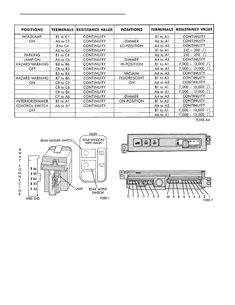
Fig. 28 Headlamp POD Switch Continuity Test

Fig. 29 Rear Wiper/Washer Control POD Switch

.

INSTRUMENT PANEL AND GAUGES

8E - 13

(a) The left most detent is OFF position.
(b) The second detent from the left is the ON

position. The ON position supplies power to the
switch in the rear passenger compartment. When the
switch is in any other position than ON, the rear
passenger compartment switch is over ridden.

(c) The third detent from the left is the Low

position.

(d) The fourth detent at the full right is the High

position.

ACCESSORY SWITCH CARRIER TEST

(1) Remove switch, refer to switch replacement.
(2) Using a volt/ohm meter, refer to Fig. 31 for

testing of wire end of connector while connected to
switch.

(3) Refer to Fig. 32 to test A/C heater switch. If

continuity is not correct replace A/C heater switch.

ACCESSORY SWITCH CARRIER REPLACEMENT

(1) Remove center bezel using a trim stick from

instrument panel (Fig. 33).

(2) Remove ash receiver lamp socket from bezel.
(3) Remove accessory switch carrier from the panel

(Fig. 30).

(4) Disconnect wire connectors and lamp.
(5) For installation reverse above procedures.

A/C AND HEATER CONTROL/BLOWER SWITCH
REPLACEMENT

(1) Remove center bezel using a trim stick from

instrument panel (Fig. 33).

(2) Remove ash receiver lamp socket from bezel.
(3) Remove cigar lighter element.
(4) Remove accessory switch carrier.

(5) Remove two screws and pull control assembly

rearward. Reach behind control and disconnect the
wiring harnesses, vacuum lines and temperature con-
trol cable (Fig. 34).

(6) For installation reverse above procedures.

A/C AND HEATER CONTROL LAMP REPLACE-
MENT

(1) Remove center bezel using a trim stick from

instrument panel (Fig. 33).

(2) Remove ash receiver lamp socket from bezel.
(3) Remove cigar lighter element.
(4) Remove accessory switch carrier.
(5) Remove two screws and pull control assembly

rearward. Reach behind control and disconnect lamp
(Fig. 34).

(6) For installation reverse above procedures.

Fig. 31 Accessory Switch Carrier Test

Fig. 32 A/C Heater Switch Test

8E - 14

INSTRUMENT PANEL AND GAUGES

.

REAR A/C-HEATER SWITCH REPLACEMENT

For the blower switch on the instrument panel, refer

to Accessory Switch Carrier Replacement (Fig. 30).

The rear A/C-heater switch assembly in the left rear

quarter trim panel (Fig. 34).

(1) Using a trim stick pry switch from left quarter

trim panel.

(2) Disconnect wire connectors.
(3) For installation reverse above procedures.

CIGAR LIGHTER REPLACEMENT

(1) Disconnect battery
(2) Remove cigar lighter element.
(3) Remove center trim bezel. Remove ash receiver

lamp and socket if a equipped.

(4) Remove

accessory

switch

carrier

attaching

screws.

(5) Remove A/C heater control attaching screws. Pull

out and disconnect the wire connector and control
cable(s).

(6) Disconnect wire connectors and lamp/socket from

rear of cigar lighter clamp.

(7) Hold outer clamp, while turning shell. Do not

lose cigar lighter shield (Fig. 36).

(8) For installation reverse above procedures.

FORWARD CONSOLE REMOVAL

(1) Remove center bezel using a trim stick from

instrument panel (Fig. 33).

(2) Remove ash receiver lamp socket from bezel.
(3) Remove filler plate (Fig. 37).
(4) Remove ash receiver/cup holding assembly from

console. Refer to Ash Receiver Assembly for removal.

(5) Remove screws attaching console to instrument

panel:
• Two upper corners

• Two behind ash receiver

Fig. 33 Center Bezel

Fig. 34 A/C Heater Control

Fig. 35 Rear A/C Heater Control Switch

.

INSTRUMENT PANEL AND GAUGES

8E - 15

• Two at the lower bracket

(6) Pull console rearward and disconnect wire con-

nector and bulb.

(7) Remove console.
(8) For installation reverse above procedures.

CENTER STORAGE MODULE REMOVAL

(1) Remove center bezel using a trim stick from

instrument panel (Fig. 33).

(2) Remove ash receiver lamp socket from bezel.

(3) Remove ash receiver/cup holding assembly from

console. Refer to Ash Receiver Assembly for removal.

(4) Open the storage bin door and remove the check

strap pins so that door swings fully open.

(5) Remove four mounting screws and storage mod-

ule.

(6) For installation reverse above procedures.

ASH RECEIVER ASSEMBLY

Depress the ash receiver/cupholder assembly stops

and remove by sliding rearward.

BODY CONTROLLER REPLACEMENT

(1) Remove steering column cover to gain access to

the body controller (Fig. 38).

(2) Disconnect the two 25-way connectors from body

controller.

(3) Remove mounting screws from body controller.
(4) Pull to the left to release body controller of S-clips

and remove unit.

(5) For installation reverse above procedures. En-

sure body controller is locked into the S-clips.

LOWER RIGHT INSTRUMENT PANEL REPLACE-
MENT

(1) Remove center console bezel using a trim stick

from instrument panel (Fig. 33).

(2) Remove accessory switch carrier.
(3) Remove heater control (Fig. 34).
(4) Disconnect cigar lighter.
(5) Remove center or forward console, refer to re-

moval procedures (Fig. 36).

(6) Remove attaching screws and right lower panel

(Fig. 39).

Fig. 36 Cigar Lighter

Fig. 37 Forward and Center Console

Fig. 38 Instrument Panel Steering Column Cover

8E - 16

INSTRUMENT PANEL AND GAUGES

.


Content   ..  210  211  212  213   ..