Chrysler Town & Country/Voyager, Dodge Caravan, Plymouth Voyager. Manual - part 210
INSTRUMENT PANEL CLUSTER LENS RE-
PLACEMENT
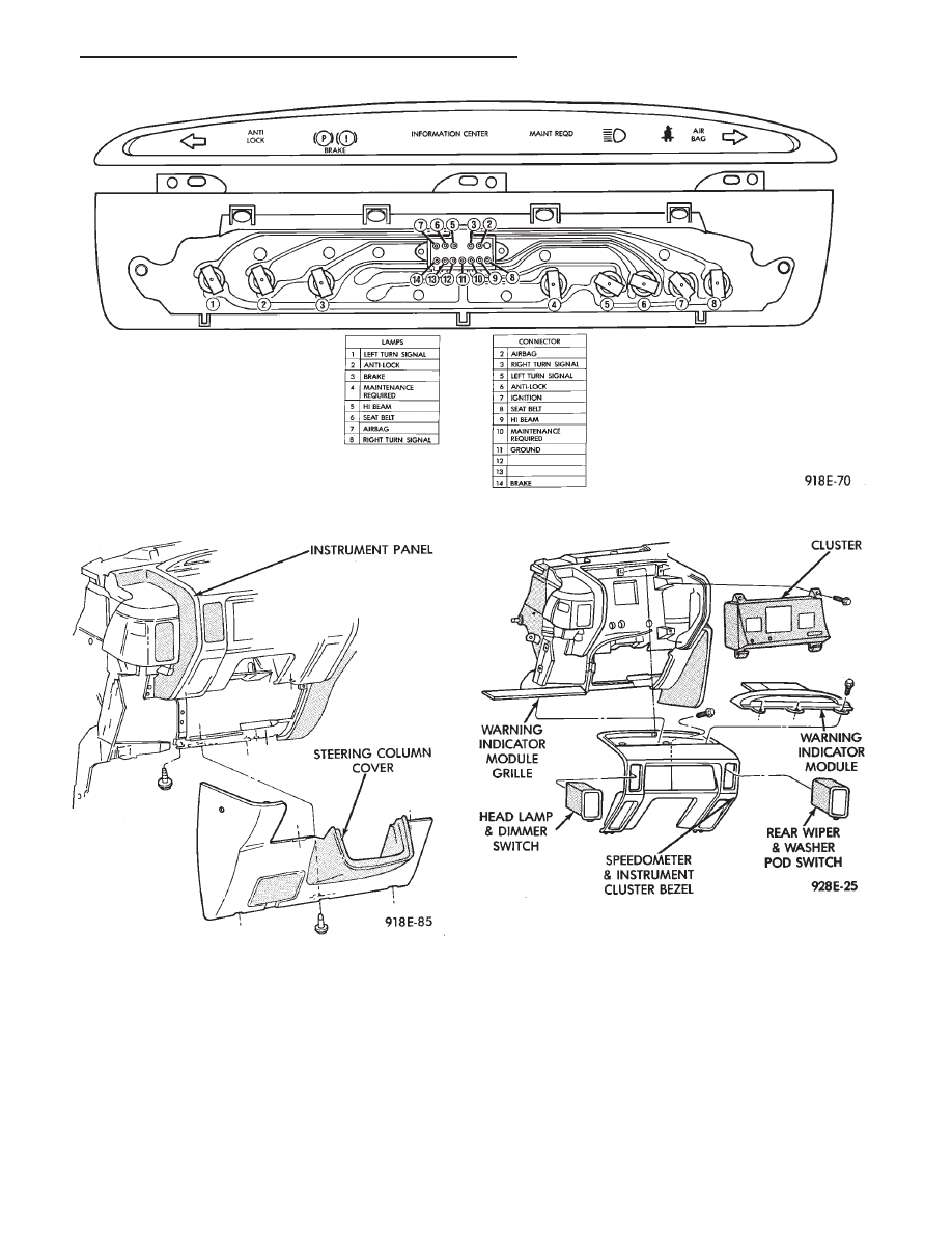
(1) Remove warning indicator grille by prying up
with a flat blade tool. (2) Remove three mounting
screws from the warning indicator module assembly
and disconnect wire connector.
(3) Remove steering column cover (Fig. 8). Set park-
ing brake and shift gear selector into low.
(4) Remove cluster bezel and disconnect wire con-
nectors.
(5) Remove six screws securing lens to cluster hous-
ing (Fig. 10).
(6) Remove lens.
(7) For installation reverse above procedures.
INSTRUMENT PANEL CLUSTER REPLACE-
MENT
(1) Remove warning indicator grille by prying up
with a flat blade tool.
(2) Remove three mounting screws from the warning
indicator module assembly and disconnect wire con-
nector.
Fig. 7 Warning Indicator Module
Fig. 8 Instrument Panel Steering Column Cover
Fig. 9 Instrument Cluster Bezel
.
INSTRUMENT PANEL AND GAUGES
8E - 5