Chrysler Town & Country/Voyager, Dodge Caravan, Plymouth Voyager. Manual - part 185


  Index      Chrysler     Chrysler Town & Country/Voyager, Dodge Caravan, Plymouth Voyager - service repair manual 1992 year


Search            


Content   ..  183  184  185  186   ..


Chrysler Town & Country/Voyager, Dodge Caravan, Plymouth Voyager. Manual - part 185


contained in the Fan Section. If the motor is noticeably
overheated(i.e., wire insulation melted, motor charred)
the system voltage may be too high. Check charging
system, see Group 8A, Battery/Starting/Charging Sys-
tem Diagnostics.

ELECTRIC FAN MOTOR TEST

EQUIPMENT REQUIRED

• Diagnostic Tool DRB II or equivalent
• Volt/Ohm Meter
• Wiring Diagrams Manual

TEST PROCEDURE

(1) Run the engine to normal operating temperature
(2) Check wiring connector in C25, C9, and C26 for

proper engagement, see Wiring Diagrams.

(3) Using a diagnostic tool, plug it into the diagnostic

connector rearward of the battery. Check the On-Board
Diagnostics (OBD) in the Single Board Engine Control
(Engine Controller) for fault codes, Refer to Group 14,
Fuel Injection for instructions.

(4) If fault code 88-12-35-55 is detected, go to Step 5.
(5) With the ignition switch in the run position, test

for battery voltage at single pin connector at the fan
relay. Voltage reading OK, go to Step 6. Voltage at 0-1
volt, go to Step 7.

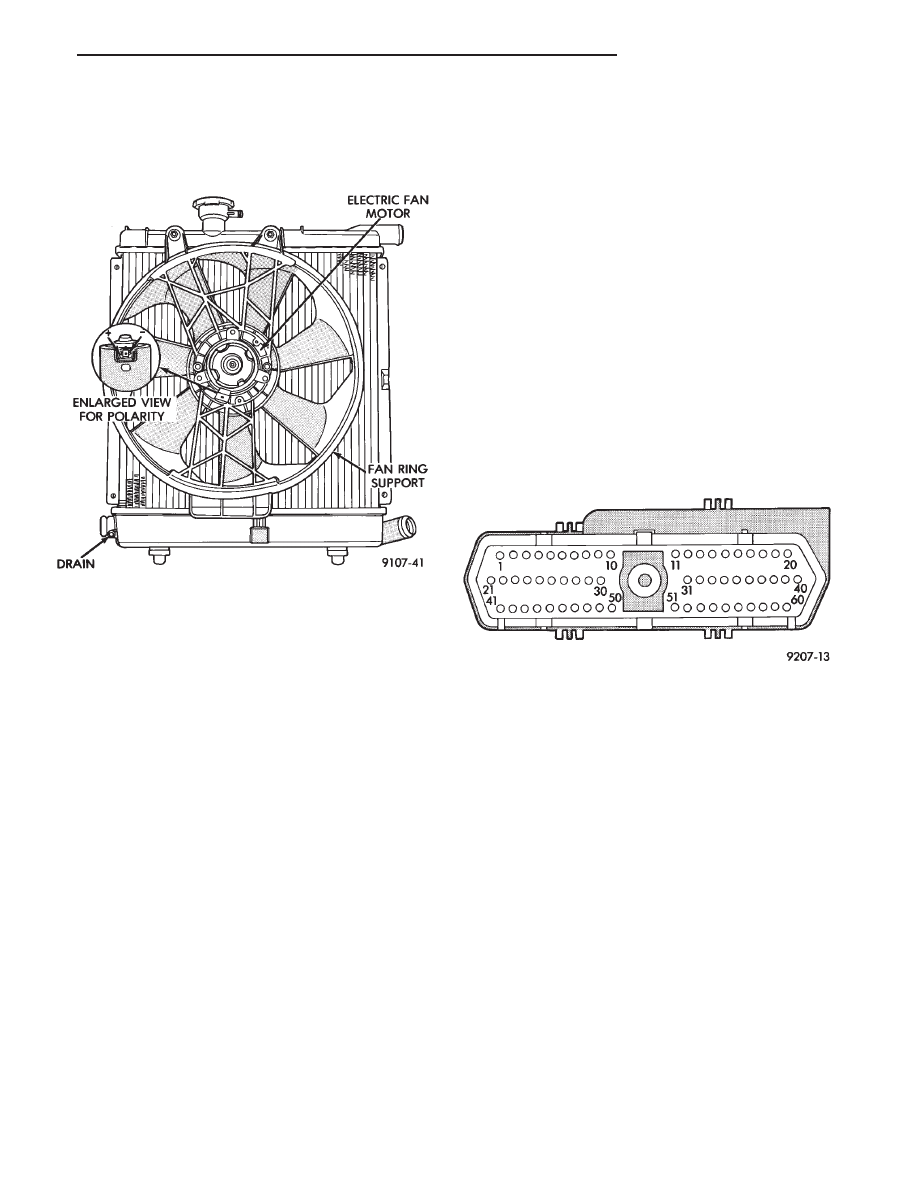
(6) With the ignition off, disconnect the 60-way con-

nector from the Engine Controller (outboard of battery)
and return the ignition to the run position. Test for
battery voltage at cavity 31 of the 60-way connector
(Fig. 7). Voltage reading OK and female terminal is not
damaged, replace the Engine Controller. Voltage read-
ing 0, repair open or short in C27 circuit.

(7) With the ignition off, disconnect the 60-way con-

nector from the Engine Controller (outboard of bat-
tery)and return the ignition to the run position. Test
for battery voltage at the single pin connector at the
fan relay. Voltage reading OK, replace the Engine
Controller. Voltage reading 0-1 volt, go to Step 7.

(8) With ignition in the run position, test for battery

voltage at the blue wire (C27) in the 3-way connector of
the fan relay. Voltage reading OK, replace the fan relay.
Voltage reading 0, repair open or short, in C27 circuit.

(9) Turn ignition off, connect the 60-way connector

at the Engine Controller, and test the system.

FAN SHROUD

These fan shrouds may cover less than full radiator

frontal area to prevent the shroud from restricting
airflow at high speeds.

The shroud supports the electric fan motor and fan.

All other non A/C vehicles have a fan motor support
assembly instead of a shroud. For removal and instal-
lation Refer to Radiator Removal Section.

AUTOMATIC TRANSMISSION OIL COOLERS

Oil coolers are of two types, internal oil to coolant

type, mounted in the radiator lower tank (Fig. 8) or
external oil-to-air type mounted ahead of the radiator,
(Fig. 8).

Rubber oil lines feed the oil cooler and the automatic

transmission. Use only approved transmission oil
cooler hose. Since these are molded to fit space avail-
able, molded hoses are recommended.

Fig. 6 Electric Fan Motor (Typical)

Fig. 7 Engine Controller 60-Way Connector from

Terminal End

.

COOLING SYSTEM

7 - 21

Fig. 8 Transmission Oil Coolers

7 - 22

COOLING SYSTEM

.

ACCESSORY DRIVE BELTS

INDEX

page

page

2.5L Engine Belts Remove/Install-Adjust

. . . . . . . . 23

3.0L Engine Belts Remove/Install-Adjust

. . . . . . . . 24

3.3L Engine Accessory Drive Belt Remove/Install

25

General Information

. . . . . . . . . . . . . . . . . . . . . . . 23

GENERAL INFORMATION

PROPER BELT TENSION

Satisfactory performance of the belt driven accesso-

ries depends on proper belt tension. Belt tensioning
should be performed with the aid of a Burroughs gauge
Special Tool C-4162. Because of space limitations in the
engine compartment of front wheel drive vehicles, the
gauge may be restricted to use after the vehicle has
been raised on a hoist and the splash shield has been
removed.

Belt tensioning methods are given in order of prefer-

ence:
• Belt tension gauge method.

• Torque equivalent method.

BELT TENSION GAUGE METHOD

Use belt tensioning Special Tool Kit C-4162 for:

CAUTION: The Burroughs gauge for the Poly-V belt is
not to be used on the V-belt. These gauges are not
interchangeable.

• For conventional V-belts affix the Burroughs gauge
(Special Tool C-4162) to the belt. Adjust the belt ten-
sion for New or Used belt as prescribed in the Belt
Tension Chart. For a Poly-V belt affix the Poly-V
Burroughs gauge to the belt and then apply specified
tension to the belt as prescribed in the Belt Tension
Chart.

Adjust the belt tension for a New or Used belt as

prescribed in the Belt Tension Chart.

TORQUE EQUIVALENT METHOD

Adjustable accessory brackets provided with a 13mm

(1/2 in.) square hole for a torque wrench can use an
equivalent torque value for belt adjustment.

Equivalent torque values for adjusting these acces-

sory drive belts are specified on the Belt Tension Chart.

2.5L ENGINE BELTS REMOVE/INSTALL-ADJUST

AIR CONDITIONING COMPRESSOR

(1) Loosen the idler bracket pivot screw A and lock-

ing screws B (Fig. 2) to remove and install belt or
adjust belt tension.

ACCESSORY DRIVE BELTS DIAGNOSIS

.

COOLING SYSTEM

7 - 23

(2) Adjust belt tension by applying torque to square

hole C on idler bracket. Adjust tension to specification
given in Belt Tension Chart.

(3) Tighten in order, first, locking screws B then

pivot screw A to 54 N

Im (40 ft. lbs.).

POWER STEERING PUMP—S TYPE

(1) From on top of the vehicle loosen locking screw G.
(2) From under the vehicle loosen the pivot screw

and pivot nut H.

(3) After installing a new belt adjust belt tension

with 1/2 in. breaker bar installed in adjusting bracket.
See tension specification in Belt Tension Chart.

(4) Tighten locking screw G to 54 N

Im (40 ft. lbs.).

(5) Tighten pivot screw H and the pivot nut to 54

N

Im (40 ft. lbs.)

ALTERNATOR BELT

(1) Loosen alternator pivot nut D.
(2) Loosen T-Bolt locking nut E and adjusting screw

F to remove and install Poly V belt or adjust belt
tension.

(3) Tighten pivot nut D TO 54 N

Im (40 ft. lbs.).

(4) Tighten adjusting screw F to adjust belt tension

to specification shown in Belt Tension Chart.

(5) Tighten T-Bolt locking nut E to 54 N

Im (40 ft.

lbs.)

3.0L ENGINE BELTS REMOVE/INSTALL-ADJUST

AIR CONDITIONING BELT

To remove and install the air conditioning compres-

sor drive belt, first loosen the idler pulley lock nut, then
turn the adjusting screw to raise or lower the idler
pulley (Figs. 3 and 4).

To adjust the air conditioning drive belt, loosen

the idler pulley nut (Fig. 3) and adjust belt tension by
tightening adjusting screw (Figs. 3 and 4). Tighten
pulley nut to 54 N

Im (40 ft. lbs.) after adjustment.

Fig. 1 Drive Belt Inspection

Fig. 2 Accessory Drive Belts 2.5L Engine

7 - 24

COOLING SYSTEM

.


Content   ..  183  184  185  186   ..