Chrysler Town & Country/Voyager, Dodge Caravan, Plymouth Voyager. Manual - part 151


  Index      Chrysler     Chrysler Town & Country/Voyager, Dodge Caravan, Plymouth Voyager - service repair manual 1992 year


Search            


Content   ..  149  150  151  152   ..


Chrysler Town & Country/Voyager, Dodge Caravan, Plymouth Voyager. Manual - part 151


INSTALLATION

(1) Install outer overrunning clutch race and retain-

ing snap ring.

(2) Install overrunning clutch spacers and snap ring.

CAUTION: The overrunning clutch can be installed
backwards.

(3) To check for proper installation of the overrun-

ning clutch, temporally install the inner race into the
overrunning clutch with the tapered end going in first
(Fig. 16). The inner race should spin when turned
counterclockwise (Fig. 17) and grab when turned clock-
wise (Fig. 18).

(4) Install dog clutch onto shaft and reinstall snap

ring.

(5) Install overrunning clutch on the shaft with the

tapered end facing outward and install snap ring.

(6) Clean all sealing surfaces. Apply a bead of Mo-

par

t Gasket Maker, Loctite Gasket Eliminator or

equivalent. Then reinstall the overrunning clutch case
to the rear carrier case. Install retaining bolts and
tighten to 28 N

Im (250 in. lbs.).

(7) Apply Mopar

t Gasket Maker, Loctite Gasket

Eliminator or equivalent and reinstall cover. When
installing cover be sure that the overrunning clutch
fork engages into the overrunning clutch dog.

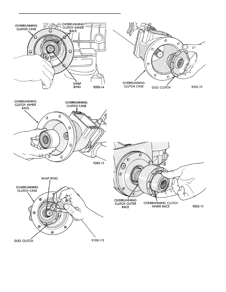
Fig. 12 Inner Race Snap Ring Removal

Fig. 13 Remove Overrunning Clutch Race

Fig. 14 Dog Clutch Snap Ring

Fig. 15 Dog Clutch Removal

Fig. 16 Temporally Install Inner Race

.

REAR SUSPENSION AND DRIVELINE

3 - 31

(8) Install rear drive line module assembly into the

vehicle.

(9) Check and fill fluid levels as required.

OVERRUNNING CLUTCH CASE

REMOVAL

(1) Remove rear drive line module assembly.
(2) Remove overrunning clutch cover assembly.
(3) Drain fluid from overrunning clutch case.
(4) Remove overrunning clutch case to rear carrier

case bolts (Fig. 19).

(5) Separate the overrunning clutch housing from

the rear carrier housing.

(6) Remove overrunning clutch inner race snap ring

(Fig. 20).

(7) Slide overrunning clutch inner race off of the

shaft.

(8) Remove dog-clutch snap ring and slide dog-clutch

off of the shaft.

(9) Remove torque shaft rear bearing snap ring.
(10) Remove torque tube retaining bolts (Fig. 21).

(11) Separate overrunning clutch case from torque

tube.

(12) Remove rear bearing retaining snap ring in

overrunning clutch case (Fig. 22).

(13) Remove rear torque shaft bearing.
(14) Drive out front overrunning clutch seal with

special tool C-4967 (Fig. 23).

INSTALLATION

(1) Install new seal with special tool MD998334.

Seal should be flush with outside edge of housing (Fig.
24).

(2) Install rear torque shaft bearing and snap ring.
(3) Install overrunning clutch case onto torque tube.

Tighten bolts to 28 N

Im (250 in. lbs.).

(4) Install torque shaft snap ring.

Fig. 17 Turn Inner Race Counterclockwise

Fig. 18 Turn Inner Race Clockwise

Fig. 19 Overrunning Clutch Case to Rear Carrier

Bolts

Fig. 20 Inner Race Snap Ring

3 - 32

REAR SUSPENSION AND DRIVELINE

.

(5) Slide dog clutch onto shaft and install snap ring.
(6) Slide overrunning clutch inner race onto shaft

and install retaining snap ring.

(7) Clean all sealing surfaces. Then apply a bead of

Mopar

t Gasket Maker, Loctite Gasket Eliminator or

equivalent. Then reinstall the overrunning clutch case
to the rear carrier case. Install retaining bolts and
tighten to 28 N

Im (250 in. lbs.).

(8) Apply Mopar

t Gasket Maker, Loctite Gasket

Eliminator or equivalent and reinstall vacuum shift

cover. When installing cover be sure that the overrun-
ning clutch fork engages into the overrunning clutch
dog.

(9) Install rear drive line module into vehicle.
(10) Check and fill all fluid levels as required.

PROPELLER SHAFT SERVICE

The propeller shaft is a hollow shaft with a plunging

tripod joint on the front of the shaft and a fixed tripod
joint on the rear of the shaft. There are no serviceable
parts. The shaft is serviced as an assembly. The flange
patterns are different at each end to prevent installing
the shaft backwards.

REMOVAL AND INSTALLATION

(1) Place vehicle in neutral and lift vehicle on hoist.

CAUTION:Do not allow end of propeller shaft to hang
free.

(2) Remove propeller shaft rear mounting bolts and

support end of propeller shaft (Fig. 1).

(3) Remove propeller shaft front mounting bolts and

remove propeller shaft assembly (Fig. 2)

CAUTION: Do not allow the propeller shaft to hang
freely while installing.

Fig. 21 Torque Tube Bolts

Fig. 22 Torque Shaft Rear Bearing Snap Ring

Fig. 23 Seal Removal

.

REAR SUSPENSION AND DRIVELINE

3 - 33

(4) To Install, Reverse Removal Procedure. Be sure

flange mating faces are clean.

HALF SHAFT SERVICE

The half shaft assemblies are three piece units. Each

half shaft has one tripod joint at each end and a solid
interconnecting shaft. The procedure to recondition the
inner or outer joint is identical.

Note that lubricant requirements and quantities

could be different than other axle shaft joints located

on the vehicle. Only use the correct lubricant and
amount supplied with the boot package or joint. Do not
use standard wheel bearing grease or other lubricants,
joint failure will result.

REMOVAL AND INSTALLATION

(1) Lift vehicle on hoist so that the wheels hang

freely.

(2) Remove rear wheel.
(3) Remove cotter pin, nut lock and spring washer

(Fig. 3).

(4) Remove hub nut and washer.

CAUTION: The half shaft outer C.V. joint, when in-
stalled, acts as a bolt and secures the hub/bearing
assembly. If the vehicle is to be supported or moved
on its wheels, install and torque a bolt through the
hub. This will insure that the hub/bearing assembly
cannot loosen.

(5) Remove inner half shaft retaining bolts (Fig. 4).

Fig. 24 Installing New Seal

Fig. 1 Propeller Shaft Mounting Bolts (Rear)

Fig. 2 Propeller Shaft Bolts (Front)

Fig. 3 Cotter Pin, Nut Lock, and Spring Washer

3 - 34

REAR SUSPENSION AND DRIVELINE

.


Content   ..  149  150  151  152   ..