Chrysler Town & Country/Voyager, Dodge Caravan, Plymouth Voyager. Manual - part 129


  Index      Chrysler     Chrysler Town & Country/Voyager, Dodge Caravan, Plymouth Voyager - service repair manual 1992 year


Search            


Content   ..  127  128  129  130   ..


Chrysler Town & Country/Voyager, Dodge Caravan, Plymouth Voyager. Manual - part 129


(4) If the high pressure gauge reads below 2963 kPa

(430 psi)

6138 kPa (20 psi) the compressor clutch

should be engaged.

CAUTION: Do not allow engine to overheat when
radiator air flow is blocked.

(5) Block radiator air flow with a suitable cover to

increase the high side pressure to at least 3100 kPa
(450 psi). Compressor clutch should disengage.

(6) Remove cover from front of vehicle to allow high

side pressure to decrease. When pressure drops below
1826 kPa (265 psi), compressor clutch should engage.

If High Pressure Cut-Out Switch is defective, replace

it.

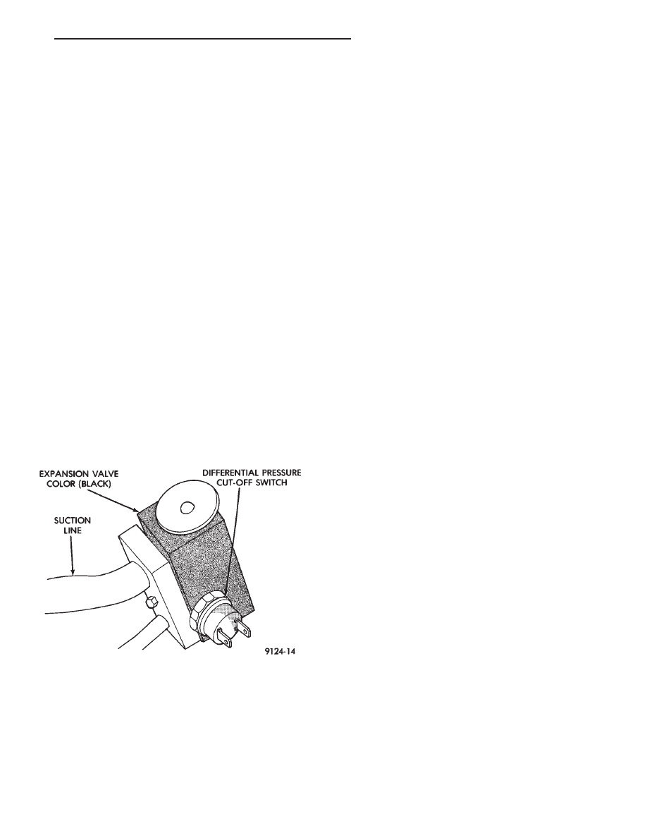
BLACK EXPANSION VALVE TEST

Review Safety Precautions and Warnings in the

General Information section of this Group. The work
area temperature must be 21°C to 27°C (70°F to 85°F)
when testing expansion valve. To test the expansion
valve:

(1) Connect a charging station or manifold gauge set

to the refrigerant system service ports. Verify the
refrigerant charge level using the sight glass method.

(2) Disconnect and plug the vacuum line at the

water control valve.

(3) Disconnect the wire connector at the differential

pressure cut-off switch. Using a jumper wire, jump
across the terminals inside the connector boot (Fig. 5).

(4) Close all doors, windows and vents to the passen-

ger compartment.

(5) Set heater-A/C control to A/C, full heat, FLOOR,

and high blower. System should be in a recirculation
mode with reheat. This is not possible with control.

(6) Remove lower right side of panel and switch the

two vacuum lines to allow reheat with recirculation.

(7) Start the engine and allow to idle (1000 R.P.M.).

After the engine has reached running temperature,
allow the passenger compartment to heat up to create
the need for maximum refrigerant flow into the evapo-
rator.

(8) Discharge (high pressure) gauge should read 965

to 1655 kPa (140 to 240 psi) when the refrigerant
charge is sufficient. If system cannot achieve proper
pressure, replace the expansion valve. If pressure is
correct, record reading and proceed with test.

WARNING: PROTECT SKIN AND EYES FROM CON-
TACTING CO

2

PERSONAL INJURY CAN RESULT.

(9) If discharge pressure is within specified range,

freeze the expansion valve control head for 30 seconds.
Use a super cold substance (liquid CO

2

).Do not spray

R-12 Refrigerant on the expansion valve for this
test. 
If compressor discharge (high) pressure does not
drop by 15% or more of the pressure recorded in step 8,
replace the expansion valve. Allow the expansion valve
to thaw. The discharge pressure should stabilize to the
pressure recorded in step 8. If the pressure does not
stabilize, replace the expansion valve.

(10) Correct water valve vacuum line and recirc.

actuator lines. Install lower right panel.

HIGH PRESSURE RELIEF VALVE (HPR) DIAGNOSIS

The HPR valve prevents damage to the air-

conditioning system if excessive pressure develops.
Excessive pressure can caused by condenser air flow
blockage, refrigerant overcharge, or air and moisture
in the system.

HPR VALVE LOCATION

The HPR Valve is located on the compressor end

plate. (Fig. 6).

The high pressure relief valve vents only a small

amount of refrigerant necessary to reduce system pres-
sure and then reseats itself. The majority of the refrig-
erant is conserved in the system. The valve is cali-
brated to vent at a pressure of 3100 to 4140 Kpa (450 to
600 psi). If a valve has vented a small amount of
refrigerant, it does not necessarily mean the valve is
defective.

For (HPR) valve replacement, refer to Variable Dis-

placement Compressor Service Procedures.

Fig. 5 Differential Pressure Cut-Out Switch

.

HEATING AND AIR CONDITIONING

24 - 11

Fig. 6 High Pressure Relief Valve—Variable Dis-

placement Compressor

24 - 12

HEATING AND AIR CONDITIONING

.

FIXED DISPLACEMENT COMPRESSOR AND COMPONENTS DIAGNOSTIC PROCE-

DURES

INDEX

page

page

Clutch Coil Tests

. . . . . . . . . . . . . . . . . . . . . . . . . 13

Compressor Clutch Inoperative

. . . . . . . . . . . . . . . 13

Compressor Identification

. . . . . . . . . . . . . . . . . . . 13

Compressor Noise

. . . . . . . . . . . . . . . . . . . . . . . . 13

Electronic Cycling Clutch Switch

. . . . . . . . . . . . . . 15

Expansion Valve Tests (Silver Colored Expansion Valve)

. . . . . . . . . . . . . . . . . . . . . . . . . . . . . . . . . . . . . . 15

Fixed Displacement Compressor Refrigerant

System

. . . . . . . . . . . . . . . . . . . . . . . . . . . . . . . 15

General Information

. . . . . . . . . . . . . . . . . . . . . . . 13

High Pressure Relief Valve (HPR) Diagnosis

. . . . . 17

Low-Pressure Cut-Off Switch Diagnosis

. . . . . . . . 13

GENERAL INFORMATION

COMPRESSOR IDENTIFICATION

COMPRESSOR NOISE

Excessive

noise

that

occurs

when

the

air-

conditioning is being used, can be caused by loose bolts,
mounting brackets, loose clutch, or excessive high
refrigerant system operating pressure. Verify compres-
sor drive belt condition, proper refrigerant charge and
head pressure before compressor repair is performed.

For noise diagnostic procedures, refer to the Com-

pressor Noise and Compressor Clutch Diagnosis chart
in this section.

COMPRESSOR CLUTCH INOPERATIVE

The air-conditioning compressor clutch electrical cir-

cuit is controlled by the engine controller computer. It
is located in the engine compartment outboard of the
battery.

If the compressor clutch does not engage:
Verify refrigerant charge.
If the compressor clutch still does not engage check

for battery voltage at the low pressure or differential
pressure cut-off switch located on the expansion valve.
If voltage is not detected, refer to:
• Group 8W, Wiring diagrams.

• The appropriate Powertrain Diagnostic Procedures
manual for diagnostic information.

If voltage is detected at the cut-off switch, connect

switch and check for battery voltage between the
compressor clutch connector terminals.

If voltage is detected, perform A/C Clutch Coil Tests.

CLUTCH COIL TESTS

(1) Verify battery state of charge. (Test indicator in

battery should be green).

(2) Connect an ammeter (0-10 ampere scale) in se-

ries with the clutch coil terminal. Use a volt meter
(0-20 volt scale) with clip leads measuring voltage
across the battery and A/C clutch.

(3) With A/C control in A/C mode and blower at low

speed, start the engine and run at normal idle.

(4) The A/C clutch should engage immediately and

the clutch voltage should be within two volts of the
battery voltage. If the A/C clutch does not engage, test
the fusible link.

(5) The A/C clutch coil is acceptable if the current

draw is 2.0 to 3.7 amperes at 11.5-12.5 volts at clutch
coil. This is with the work area temperature at 21°C
(70°F). If voltage is more than 12.5 volts, add electrical
loads by turning on electrical accessories until voltage
reads below 12.5 volts.

If coil current reads zero, the coil is open and should

be replaced. If the ammeter reading is 4 amperes or
more, the coil is shorted and should be replaced. If the
coil voltage is not within two volts of the battery
voltage, test clutch coil feed circuit for excessive volt-
age drop.

LOW-PRESSURE CUT-OFF SWITCH DIAGNOSIS

The Low Pressure Cut-Off (LPCO) Switch (Fig. 2)

monitors the refrigerant gas pressure on the suction
side of the system. The LPCO is located on the ex

[

Fig. 1 Fixed Displacement Compressor—Model

10PA17

.

HEATING AND AIR CONDITIONING

24 - 13

COMPRESSOR NOISE AND COMPRESSOR CLUTCH DIAGNOSIS

24 - 14

HEATING AND AIR CONDITIONING

.


Content   ..  127  128  129  130   ..