Chrysler Town & Country/Voyager, Dodge Caravan, Plymouth Voyager. Manual - part 128


  Index      Chrysler     Chrysler Town & Country/Voyager, Dodge Caravan, Plymouth Voyager - service repair manual 1992 year


Search            


Content   ..  126  127  128  129   ..


Chrysler Town & Country/Voyager, Dodge Caravan, Plymouth Voyager. Manual - part 128


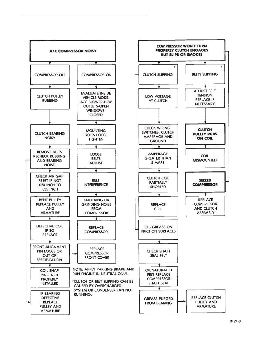
COMPRESSOR NOISE AND COMPRESSOR CLUTCH DIAGNOSIS

.

HEATING AND AIR CONDITIONING

24 - 7

If the compressor clutch does not engage:
Verify refrigerant charge.
If the compressor clutch still does not engage:
Check for battery voltage at the differential pressure

cut-off switch located on the expansion valve. If voltage
is not detected, refer to:

(1) Group 8W, Wiring Diagrams.
(2) The appropriate Powertrain Diagnostic Proce-

dures manual for diagnostic information.

(3) The Compressor Clutch Diagnosis—Variable

Displacement Compressor chart in this section.

If voltage is detected at the cut-off switch, connect

switch and check for battery voltage between the
compressor clutch connector terminals.

If voltage is detected, perform A/C Clutch Coil Tests.

CLUTCH COIL TESTS

(1) Verify battery state of charge. (Test indicator in

battery should be green).

(2) Connect an ammeter (0-10 ampere scale) in se-

ries with the clutch coil terminal. Use a volt meter
(0-20 volt scale) with clip leads measuring voltage
across the battery and A/C clutch.

(3) With A/C control in A/C mode and blower at low

speed, start the engine and run at normal idle.

(4) The A/C clutch should engage immediately and

the clutch voltage should be within two volts of the
battery voltage. If the A/C clutch does not engage, test
the fusible link.

(5) The A/C clutch coil is acceptable if the current

draw is 2.0 to 3.7 amperes at 11.5-12.5 volts at clutch
coil. This is with the work area temperature at 21°C
(70°F). If voltage is more than 12.5 volts, add electrical
loads by turning on electrical accessories until voltage
reads below 12.5 volts.

If coil current reads zero, the coil is open and should

be replaced. If the ammeter reading is 4 amperes or
more, the coil is shorted and should be replaced. If the
coil voltage is not within two volts of the battery
voltage, test clutch coil feed circuit for excessive volt-
age drop.

DIFFERENTIAL PRESSURE CUT-OUT SWITCH DI-
AGNOSIS

The Differential Pressure Cut-Out (DPCO) Switch

(Fig. 2) monitors the liquid refrigerant pressure on the
liquid side of the system. The DPCO is located on the
expansion valve. The expansion valve is black in color
when a variable displacement compressor is used. The
DPCO turns off voltage to the compressor clutch coil
when liquid refrigerant pressure drops to levels that
could damage the compressor. The DPCO is a sealed
factory calibrated unit. It must be replaced if defective.

DPCO SWITCH TEST

The work area temperature must not be below 10°C

(50°F) to test the compressor clutch circuit.

(1) With gear selector in park or neutral, and park

brake set, start engine and allow to idle.

(2) Raise hood and disconnect DPCO switch connec-

tor boot.

(3) Using a suitable jumper wire, jump across the

terminals inside wire connector boot.

(4) If clutch does not engage, the wiring, fuse, relay,

ambient switch, or high pressure cut-off switch can be
defective. Refer to Group 8W, Wiring Diagrams.

(5) If clutch engages, connect a suitable manifold

gauge set. Read low pressure gauge. At pressure 283
kPa (41 psi) and above, DPCO switch will complete the
clutch circuit. If the low pressure gauge reads below
317 kPa (46 psi), the system is low on refrigerant
charge or empty due to a leak.

(6) Install connector boot on switch and repeat step

number 3. If the clutch does not engage, replace the
DPCO switch.

AMBIENT SWITCH DIAGNOSIS

The ambient switch is a temperature sensor located

in front of the condenser behind the grille. The ambient
switch prevents the compressor from engaging in cold
temperatures. The ambient switch is a sealed factory
calibrated unit. It must be replaced if defective.

AMBIENT SWITCH TEST

(1) Disconnect ambient switch wire connector.
(2) Using a suitable ohm meter or continuity tester,

test for continuity across the ambient switch termi-
nals.

(a) At temperature above 10°C (50°F), the switch

circuit should be complete.

(b) Chill the switch with ice to below 10°C (50°F)

and test for continuity. The switch circuit should be
open, with continuity not detected.
Replace ambient switch if defective.

CONDENSER FAN CONTROL SWITCH DIAGNOSIS

The Fan Control Switch is located on the plumbing

discharge line at the A/C compressor (Fig. 3). The fan
control switch cycles the radiator/condenser fan on and
off by monitoring the compressor discharge pressure.
The radiator top tank temperature sensor can over ride
the function of the fan control switch. It will cycle the
radiator/condenser fan on and off depending on the
engine coolant temperature.

FAN CONTROL SWITCH TEST

Review Safety Precautions and Warnings in the

General Information section of this Group before pro-
ceeding with this operation. Connect a suitable man-

24 - 8

HEATING AND AIR CONDITIONING

.

COMPRESSOR CLUTCH DIAGNOSIS—VARIABLE DISPLACEMENT COMPRESSOR—MODEL 6C17

.

HEATING AND AIR CONDITIONING

24 - 9

ifold gauge set to the refrigerant system service ports.
Work area temperature can not be below 21°C (70°F).

WARNING:

AVOID

RADIATOR/CONDENSER

FAN

BLADES WHEN WORKING IN THE RADIATOR AREA.
FAN IS CONTROLLED BY TEMPERATURE AND CAN
START ANY TIME IGNITION IS ON. PERSONAL IN-
JURY CAN RESULT.

(1) Disconnect fan control switch wire connector.
(2) Using a suitable jumper wire, jump across termi-

nals in wire connector.

(3) Connect a suitable continuity tester across fan

control switch terminals.

(4) Start engine and set idle at 1300 rpm. The

radiator fan should run constantly.

(5) Set the A/C controls to A/C and high blower.
(6) If the high pressure gauge reads below 1102 kPa

(160 psi) there should be no continuity across the
switch terminals.

CAUTION: Do not allow engine to overheat when
radiator air flow is blocked.

(7) Block radiator air flow with a suitable cover to

increase the high side pressure to at least 1585 kPa
(230 psi). Electrical continuity should be detected
across the fan control switch terminals.

(8) Remove cover from front of vehicle to allow high

side pressure to decrease. When pressure drops below
1102 kPa (160 psi), continuity should cease.

If fan control switch is defective, replace it.

HIGH PRESSURE CUT-OUT SWITCH DIAGNOSIS

The High Pressure Cut Out (HPCO) switch is located

on the rear cover of the Variable Displacement Com-
pressor (Fig. 4). The function of the switch is to
disengage the compressor clutch by monitoring the
compressor discharge (high) pressure. The HPCO
Switch is in the same circuit as the Differential Pres-
sure Cut Out (DPCO) switch and Ambient Switch.

HPCO SWITCH TESTS

Review Safety Precautions and Warnings in the

General Information section before proceeding with
this operation.

Connect a suitable manifold gauge set to the refrig-

erant system service ports. Work area temperature can
not be below 21°C (70°F).

(1) Raise hood of vehicle.
(2) With gear selector in park or neutral, and park

brake set, start engine and allow to idle at 1300 rpm.

(3) Set the A/C controls to A/C and High blower.

Fig. 2 Differential Pressure Cut-Out Switch

Fig. 3 Condenser Fan Control Switch

Fig. 4 Variable Displacement Compressor—Model

6C17

24 - 10

HEATING AND AIR CONDITIONING

.


Content   ..  126  127  128  129   ..