Chrysler Town & Country/Voyager, Dodge Caravan, Plymouth Voyager. Manual - part 122


  Index      Chrysler     Chrysler Town & Country/Voyager, Dodge Caravan, Plymouth Voyager - service repair manual 1992 year


Search            


Content   ..  120  121  122  123   ..


Chrysler Town & Country/Voyager, Dodge Caravan, Plymouth Voyager. Manual - part 122


FRONT DOOR BELT MOLDING AND
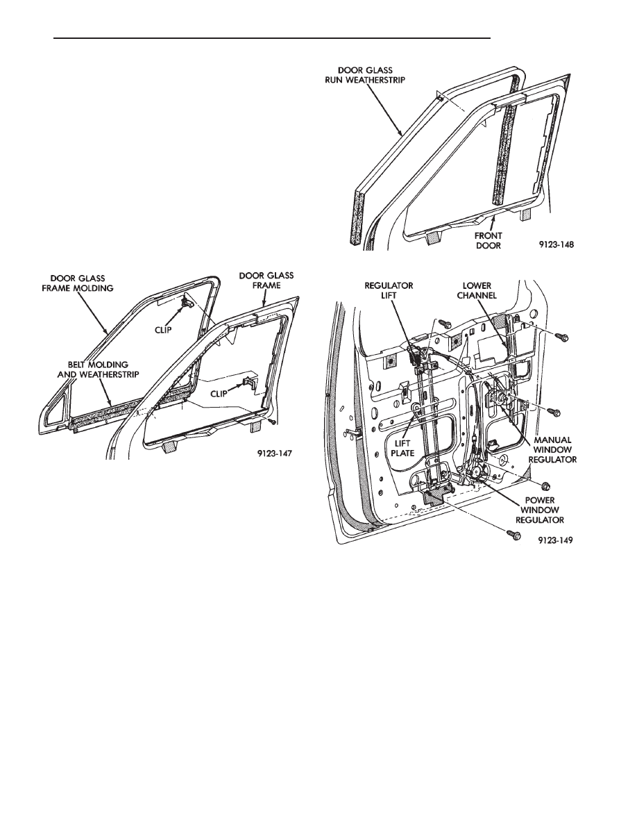
WEATHERSTRIP—WAGON

REMOVAL (FIG. 20)

(1) Remove door glass.
(2) Remove side view mirror.
(3) Remove door glass run weatherstrip.
(4) Disengage clips holding door frame molding to

door frame.

(5) Remove screws holding belt molding and weath-

erstrip to door panel.

(6) Separate belt molding and weatherstrip from

door.

INSTALLATION

Reverse the preceding operation.

FRONT DOOR GLASS CHANNEL AND RUN WEATH-
ERSTRIP

REMOVAL (FIG. 21)

(1) Lower door glass to down position.
(2) Remove side view mirror as necessary to gain

clearance for weatherstrip removal.

(3) Pull glass run weatherstrip from door frame

channel.

INSTALLATION

Reverse the preceding operation.

FRONT DOOR GLASS LOWER CHANNEL

REMOVAL (FIG. 22)

(1) Remove door trim panel and water shield.
(2) Raise glass to up position.
(3) Remove bolts holding channel to inner door

panel.

(4) Separate channel from door.

INSTALLATION

Reverse the preceding operation.

FRONT DOOR WINDOW REGULATOR—MANUAL

REMOVAL (FIG. 22)

(1) Remove door trim panel and water shield.
(2) Remove bolts holding door glass to window lift

plate.

(3) Allow glass to rest on bottom of door.
(4) Remove bolts holding regulator to door inner

panel.

(5) Disengage push-in fastener holding regulator

cables to inner door panel.

Fig. 20 Belt Molding and Weatherstrip—Wagon Only

Fig. 21 Glass Channel and Run Weatherstrip

Fig. 22 Front Lower Channel and Window Regulator

.

BODY

23 - 27

(6) Separate regulator from door.

MANUAL WINDOW REGULATOR INSTALLA-
TION

Reverse the preceding operation.

FRONT DOOR WINDOW REGULATOR—POWER

REMOVAL (FIG. 22)

(1) Remove door trim panel and water shield.
(2) Remove bolts holding door glass to window lift

plate.

(3) Disconnect battery negative cable.
(4) Allow glass to rest on bottom of door.
(5) Disconnect power window regulator motor wire

connector. Disengage push-in fastener holding wire
harness to inner door panel.

(6) Remove bolts holding regulator to door inner

panel.

(7) Disengage push-in fastener holding regulator

cables to inner door panel.

(8) Separate regulator from door.

INSTALLATION

Reverse the preceding operation.

SLIDING DOOR TRIM PANEL

REMOVAL (FIG. 23)

(1) Close sliding door. From inside vehicle perform

the following.

(2) Remove screw plug at rearward center of door

trim and remove screw.

(3) Remove hidden screw from upper rearward cor-

ner of carpet insert.

(4) Remove screws holding trim to door from along

bottom of trim panel.

(5) Disengage trim clips holding trim to door from

around perimeter of trim panel.

(6) Lift trim panel upward to disengage barbed re-

tainers holding top of trim to door flange.

(7) Separate trim panel from sliding door.

INSTALLATION

Reverse the preceding operation.

SLIDING DOOR FRAME UPPER MOLDING

REMOVAL (FIG. 23)

(1) Remove sliding door trim panel.
(2) Remove screw plugs from upper door frame

molding.

(3) Remove screws holding upper molding to door

frame.

(4) Separate molding from door frame.

INSTALLATION

Reverse the preceding operation.

SLIDING DOOR PULL HANDLE

REMOVAL (FIG. 23)

(1) Remove sliding door trim panel.
(2) Remove upper door frame molding.
(3) Remove screw holding top of pull handle to door

frame.

(4) Remove bolts holding pull handle to inner door

panel.

(5) Separate pull handle from door.

INSTALLATION

Reverse the preceding operation.

SLIDING DOOR

REMOVAL

When removing the sliding door as an assembly it is

not necessary to loosen bolts that would alter the
alignment.

(1) Remove sliding door upper track cover.
(2) Remove upper track over travel stop.
(3) Remove sliding door sill plate.
(4) Remove lower track over travel stop.
(5) Remove sliding door center track cover.
(6) Remove center track over travel stop.
(7) With assistance, roll the door rearward and dis-

engage hinge rollers from tracks.

(8) Separate sliding door from vehicle.

Fig. 23 Sliding Door Trim and Pull Handle

23 - 28

BODY

.

SLIDING DOOR INSTALLATION

Reverse the preceding operation.

SLIDING DOOR CENTER HINGE TRACK COVER

REMOVAL (FIG. 24)

(1) Open liftgate.
(2) Remove screws holding center track cover to

quarter panel from above right taillamp.

(3) Open sliding door.
(4) Remove screws holding center track cover to

quarter panel from above sliding door rear latch
striker.

(5) Disengage clips holding track cover to quarter

panel.

(6) Separate track cover from vehicle.

INSTALLATION

Reverse the preceding operation.

SLIDING DOOR CENTER HINGE

REMOVAL (FIG. 25)

(1) Remove sliding door center hinge track cover.
(2) Remove screw holding over travel stop to center

hinge track (Fig. 24).

(3) Remove sliding door trim panel.

(4) Mark hinge location on sliding door for reference

points when installing.

(5) Support Sliding door on a suitable lifting device.
(6) Remove bolts holding center hinge to sliding

door.

(7) Separate hinge from door.
(8) Slide hinge rollers from open end of channel at

rear of quarter panel.

INSTALLATION

Reverse the preceding operation. Clean center track

with suitable solvent and wipe or blow dry with com-
pressed air. Lubricate track and rollers with Mopar

t

Multi-purpose Grease. Align sliding door to 6 mm
(0.240 in.) gap to edge of quarter panel and B-pillar, 7
mm (0.280 in.) gap to rocker and flush across gaps.

SLIDING DOOR UPPER HINGE

REMOVAL (FIG. 26)

(1) Remove sliding door upper frame molding and

pull handle.

(2) Remove sliding door upper track cover.
(3) Remove upper track over travel stop.
(4) Mark hinge location on sliding door for reference

points when installing.

(5) Support Sliding door on a suitable lifting device.
(6) Remove bolts holding hinge to sliding door.
(7) Separate hinge from sliding door.
(8) Slide hinge from open end of track at rear of door

opening.

Fig. 24 Sliding Door Center Track Cover and Over

Travel Stop

Fig. 25 Sliding Door Center Hinge

.

BODY

23 - 29

SLIDING DOOR UPPER HINGE INSTALLATION

Reverse the preceding operation. Align sliding door

to 6 mm (0.240 in.) gap to edge of quarter panel and
B-pillar, 7 mm (0.280 in.) gap to rocker and flush across
gaps.

SLIDING DOOR LOWER HINGE

REMOVAL (FIG. 27)

(1) Remove sliding door trim panel.
(2) Remove sliding door lower hinge cover.
(3) Remove sliding door sill plate.
(4) Remove lower track over travel stop.
(5) Mark hinge location on sliding door for reference

points when installing.

(6) Support sliding door on a suitable lifting device.

Do not allow door to contact quarter panel.

(7) Remove bolts holding hinge to mounting bracket.

If mounting bracket must be replaced, remove bolts
holding mounting bracket to sliding door.

(8) Separate hinge from sliding door.
(9) Slide hinge from open end of track at rear of door

opening.

INSTALLATION

Reverse the preceding operation. Align sliding door

to 6 mm (0.240 in.) gap to edge of quarter panel and
B-pillar, 7 mm (0.280 in.) gap to rocker and flush across
gaps.

SLIDING DOOR INSIDE LATCH/LOCK CONTROL

REMOVAL (FIG. 28)

(1) Remove sliding door trim panel and water shield.
(2) Remove screws holding inside door handle bezel

to latch/lock control assembly.

(3) Separate bezel from control.
(4) Remove bolts holding latch/lock control to inner

door panel.

(5) Pull control away from inner door panel and

disconnect linkage rods and power door lock wire
connector, if equipped.

(6) Separate control from door.

INSTALLATION

Reverse the preceding operation.

SLIDING DOOR LATCH/LOCK LINKAGE

REMOVAL (FIG. 29)

(1) Remove sliding door trim panel and water shield.
(2) Remove latch/lock control.

Fig. 26 Sliding Door Upper Hinge and Guide Wedge

Fig. 27 Sliding Door Lower Hinge

Fig. 28 Inside Latch/Lock Control

23 - 30

BODY

.


Content   ..  120  121  122  123   ..