Chrysler Town & Country/Voyager, Dodge Caravan, Plymouth Voyager. Manual - part 87


  Index      Chrysler     Chrysler Town & Country/Voyager, Dodge Caravan, Plymouth Voyager - service repair manual 1992 year


Search            


Content   ..  85  86  87  88   ..


Chrysler Town & Country/Voyager, Dodge Caravan, Plymouth Voyager. Manual - part 87


(9) Mark torque converter and drive plate with

chalk, for reassembly. Remove torque converter mount-
ing bolts.

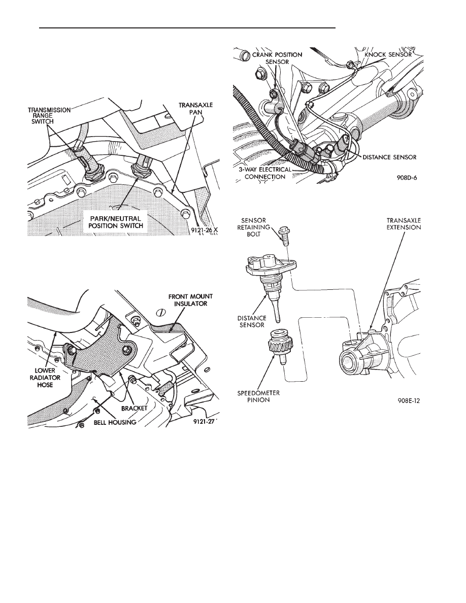
(10) Disconnect electrical connectors at PRNDL

switch and neutral safety switch (Fig. 4).

(11) Remove front engine mount insulator and

bracket.

(12) On vehicles equipped with D.I.S.ignition sys-

tem, remove crankshaft position sensor from bell hous-
ing (Fig. 6). For installation procedure refer to section
8D of this service manual.

CAUTION: Failure to remove the crankshaft position
sensor from the bell housing could cause damage to
the sensor or the torque converter drive plate during
transmission removal or installation.

(13) Disconnect and remove vehicle distance sensor

(Fig. 7).

(14) Remove starter bolts and set starter aside. Do

not allow the starter to hang from battery cable (Fig.
8).

(15) Position transmission jack securely under tran-

saxle (Fig. 9).

(16) With transmission jack in position, remove the

left transmission mount (Fig. 10).

(17) Carefully lower the transaxle assembly from

vehicle.

When installing transaxle, reverse the above proce-

dure.

Check and/or adjust gear shift cable.
Refill transaxle with MOPAR

t ATF PLUS (Auto-

matic Transmission Fluid) Type 7176 or equivalent.

Fig. 4 Disconnect PRNDL Switch and Neutral Safety

Switch

Fig. 5 Remove Front Engine Mount

Fig. 6 Remove Crank Position Sensor (D.I.S. Ignition

Only)

Fig. 7 Remove Distance Sensor

.

TRANSAXLE

21 - 97

SOLENOID ASSEMBLY-REPLACE

Fig. 8 Remove Starter Assembly

Fig. 9 Position Transmission Jack

Fig. 10 Remove Left Transmission Mount

Fig. 11 Lower Transaxle Assembly

Fig. 1 Input Speed Sensor

Fig. 2 Input Speed Sensor Removed

21 - 98

TRANSAXLE

.

PRNDL SWITCH

CAUTION: Switch seal washer must be seated prop-
erly before tightening switch. Failure to do so may

result in leakage of transmission fluid.

NEUTRAL SAFETY SWITCH

CAUTION: Switch seal washer must be seated prop-
erly before tightening switch. Failure to do so may
result in leakage of transmission fluid.

SPEED SENSOR-INPUT

CAUTION: When disconnecting speed sensor con-
nector, be sure that the weather seal does not fall off
or remain in old sensor.

The input speed sensor is located to the right of the

manual shift lever.

SPEED SENSOR-OUTPUT

The output speed sensor is located to the left of the

manual shift lever (Fig. 8).

CAUTION: When disconnecting speed sensor con-
nector, be sure that the weather seal does not fall off
or remain in old sensor.

Fig. 3 Sound Cover

Fig. 4 Attaching Screws

Fig. 5 Solenoid Assembly

Fig. 6 PRNDL Switch

Fig. 7 Neutral Safety Switch

.

TRANSAXLE

21 - 99

TRANSAXLE-RECONDITION

Prior to removing any transaxle subassemblies, plug

all openings and thoroughly clean exterior of the unit,
preferably by steam. Cleanliness through entire disas-
sembly and assembly cannot be overemphasized. When
disassembling, each part should be washed in a suit-
able solvent, then dried by compressed air. Do not
wipe parts with shop towels. 
All mating surfaces in
the transaxles are accurately machined; therefore,
careful handling of all parts must be exercised to avoid
nicks or burrs.

Fig. 8 Output Speed Sensor

Fig. 1 Oil Pan Bolts

Fig. 2 Oil Pan

Fig. 3 Oil Filter

Fig. 4 Valve Body Attaching Bolts

21 - 100

TRANSAXLE

.


Content   ..  85  86  87  88   ..