Chrysler Town & Country/Voyager, Dodge Caravan, Plymouth Voyager. Manual - part 78


  Index      Chrysler     Chrysler Town & Country/Voyager, Dodge Caravan, Plymouth Voyager - service repair manual 1992 year


Search            


Content   ..  76  77  78  79   ..


Chrysler Town & Country/Voyager, Dodge Caravan, Plymouth Voyager. Manual - part 78


REAR CLUTCH-RECONDITION

INSPECTION

Inspect facing material on all driving discs. Replace

discs that are charred, glazed or heavily pitted. Discs
should also be replaced if they show evidence of mate-
rial flaking off or if facing material can be scraped off
easily. Inspect driving disc splines for wear or other
damage. Inspect steel plate and pressure plate surface
for burning, scoring or damaged driving lugs. Re place
if necessary. Inspect plates and discs for flatness, they
must not be warped or cone-shaped.

Inspect steel plate lug grooves in clutch retainer for

smooth surfaces, plates must travel freely in the
grooves. Note ball check in piston; make sure ball
moves freely. Inspect seal rings surfaces in clutch
retainer for nicks or deep scratches; light scratches will
not interfere with sealing of the seals. Inspect neo-
prene seal rings for deterioration, wear and hardness.
Inspect piston spring and waved snap ring for distor-
tion or breakage.

Inspect teflon and/or cast iron seal rings on input

shaft for wear. Do not remove rings unless conditions

warrant. Inspect rear clutch to front clutch No. 2
thrust washer for wear. Washer thickness should be
.061 to .063 inch, replace if necessary.

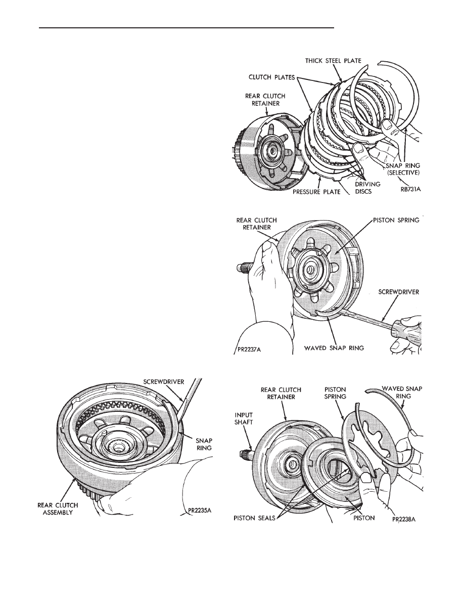
DISASSEMBLE/ASSEMBLE

Fig. 1 Rear Clutch Outer Snap Ring

Fig. 2 Rear Clutch (3-Disc Shown)

Fig. 3 Piston Spring Waved Snap Ring

Fig. 4 Rear Clutch Piston and Piston Spring

.

TRANSAXLE

21 - 61

Press out input shaft, if required.
To reassemble, reverse the above procedure.

MEASURING PLATE CLEARANCE

FRONT PLANETARY & ANNULUS
GEAR-RECONDITION

Fig. 5 Remove or Install Input Shaft Snap Ring

Fig. 6 Input Shaft Snap Ring

Fig. 1 Front Planetary Gear Snap Ring and No. 4

Thrust Washer (Always Install a New Snap Ring)

Fig. 2 Front Planetary Gear

Fig. 3 Annulus Gear Support Front Snap Ring

Fig. 7 Measuring Rear Clutch Plate Clearance

21 - 62

TRANSAXLE

.

LOW/REVERSE (REAR) SERVO-RECONDITION

To assemble, reverse the above procedure.

Fig. 4 Front Annulus Gear Support and Snap Ring

Fig. 5 Front Annulus Gear Support Snap Ring

Fig. 2 Snap Ring and Retainer

Fig. 3 Low/Reverse Servo Return Spring

Fig. 4 Low/Reverse Servo Assembly

Fig. 1 Low/Reverse Servo Snap Ring

.

TRANSAXLE

21 - 63

ACCUMULATOR-RECONDITION

To assemble, reverse the above procedure.

KICKDOWN SERVO (CONTROLLED LOAD)-
RECONDITION

Fig. 5 Accumulator Snap Ring

Fig. 6 Accumulator Plate and Snap Ring

Fig. 7 Accumulator Spring and Piston

Fig. 8 Kickdown Servo Snap Ring

Fig. 9 Kickdown Servo Rod Guide and Snap Ring

Fig. 10 Kickdown Piston Return Spring and Piston

21 - 64

TRANSAXLE

.


Content   ..  76  77  78  79   ..