Chrysler Town & Country/Voyager, Dodge Caravan, Plymouth Voyager. Manual - part 74


  Index      Chrysler     Chrysler Town & Country/Voyager, Dodge Caravan, Plymouth Voyager - service repair manual 1992 year


Search            


Content   ..  72  73  74  75   ..


Chrysler Town & Country/Voyager, Dodge Caravan, Plymouth Voyager. Manual - part 74


(4) Screw the switch with a new seal into transaxle

case and tighten to 33 N

Im (24 ft. lbs.). Retest switch

with the test lamp.

(5) Add fluid to transaxle to bring up to proper level.
(6) The back-up lamp switch circuit is through the

two outside terminals of the 3 terminal switch.

(7) To test switch, remove wiring connector from

switch and test for continuity between the two outside
pins.

(8) Continuity should exist only with transaxle in

Reverse position.

(9) No continuity should exist from either pin to the

case.

GOVERNOR

To service the governor assembly in the vehicle, it is

not necessary to remove the transfer gear cover, trans-
fer gear, and governor support. The governor may be
serviced by removing the transaxle oil pan and valve
body assembly. With the oil pan and valve body re-
moved, the governor may be unbolted from the gover-
nor support and removed from the transaxle for recon-
ditioning or replacement.

When cleaning or assembling the governor, make

sure the governor valves move freely in the bores of the
governor body.

ALUMINUM THREAD REPAIR

Damaged or worn threads in the aluminum tran-

saxle case and valve body can be repaired by the use of
Heli-Coils, or equivalent. This repair consists of drill-
ing out the worn-out damaged threads. Then tapping
the hole with a Heli-Coil tap, or equivalent, and install-
ing a Heli-Coil insert, or equivalent, into the hole. This
brings the hole back to its original thread size.

Heli-Coil, or equivalent, tools and inserts are readily

available from most automotive parts suppliers.

OIL COOLERS AND TUBES REVERSE FLUSHING

When a transaxle failure has contaminated the fluid,

the oil cooler(s) must be flushed and the cooler bypass
valve in the transaxle must be replaced. The torque
converter must also be replaced with an exchange unit.
This will insure that metal particles or sludged oil are
not transferred back into the reconditioned (or re-
placed) transaxle.

CAUTION: If vehicle is equipped with two oil coolers
(one in the radiator tank, one in front of the radiator)
they must be flushed separately. Do not attempt to
flush both coolers at one time.

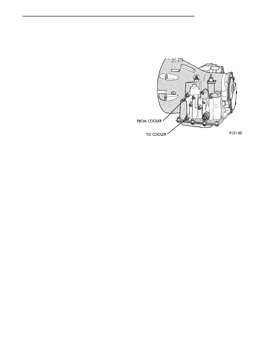
(1) Disconnect the cooler lines at the transmission.
(2) Using a hand suction gun filled with mineral

spirits, reverse flush the cooler by forcing mineral
spirits into the From Cooler line of the cooler (Fig. 1).
Catch the exiting spirits from the To Cooler line.

Observe for the presence of debris in the exiting fluid.
Continue until fluid exiting is clear and free from
debris.

(3) Using compressed air in intermittent spurts,

blow any remaining mineral spirits from the cooler,

again in the reverse direction.

(4) To remove any remaining mineral spirits from

the cooler, one (1) quart of automatic transmission fluid
should be pumped through the cooler before reconnect-
ing.

(5) If at any stage of the cleaning process, the cooler

does not freely pass fluid, the cooler must be replaced.

OIL COOLER FLOW CHECK

After the new or repaired transmission has been

installed and filled to the proper level with automatic
transmission fluid, the flow should be checked using
the following procedure:

(1) Disconnect the From cooler line at the trans-

mission and place a collecting container under the
disconnected line.

(2) Run the engine at curb idle speed, with the

shift selector in neutral.

(3) If the fluid flow is intermittent or it takes more

than 20 seconds to collect one quart of automatic
transmission fluid, the cooler should be replaced.

CAUTION: With the fluid set at the proper level, fluid
collection should not exceed (1) quart or internal
damage to the transmission may occur.

(4) If flow is found to be within acceptable limits,

reconnect the cooler line and fill transmission to the
proper level, using the approved type of automatic
transmission fluid.

Fig. 1 Cooler Line Identification

.

TRANSAXLE

21 - 45

TRANSAXLE AND TORQUE CONVERTER REMOVAL

Transaxle removal does NOT require engine

removal.

(1) The transaxle and torque converter must be

removed as an assembly; otherwise, the torque con-
verter drive plate, pump bushing, or oil seal may be
damaged. The drive plate will not support a load;
therefore, none of the weight of the transaxle should be
allowed to rest on the plate during removal.

(2) Disconnect or connect negative battery cable.
(3) Disconnect or connect throttle linkage and shift

linkage from transaxle.

If so equipped, unplug lockup torque converter

plug, located near the dipstick.

CAUTION: Raise vehicle. Remove front wheels. Refer
to ‘‘Suspension, Group 2’’ to remove or install wheel
hub nut and both drive shafts.

Remove torque converter dust cover. Mark

torque converter and drive plate with chalk, for
reassembly. Remove torque converter mounting
bolts.

Fig. 1 Remove Upper and Lower Oil Cooler Hoses

Fig. 2 Engine Support Fixture (Typical)

Fig. 3 Remove Bell Housing Upper Bolts

Fig. 4 Remove or Install Left Splash Shield

Fig. 5 Remove or Install Access Plug in Right

Splash Shield to Rotate Engine Crankshaft

21 - 46

TRANSAXLE

.

Remove or install starter. Remove or install lower

bell housing bolts.

Fig. 6 Remove or Install Wire to Neutral/Park Safety

Switch

Fig. 7 Remove or Install Engine Mount Bracket from

Front Crossmember

Fig. 8 Remove or Install Front Mount Insulator

Through-Bolt and Bell Housing Bolts

Fig. 9 Positioning Transmission Jack

Fig. 10 Remove or Install Left Engine Mount

Fig. 11 Remove or Install Left Engine Mount from

Engine

.

TRANSAXLE

21 - 47

Carefully work transaxle and torque converter as-

sembly

rearward

off

engine

block

dowels

and

disengage converter hub from end of crankshaft. At-
tach a small ‘‘C’’ clamp to edge of bell housing.
This will hold torque converter in place during
transaxle removal. 
Lower transaxle and remove as-
sembly from under the vehicle.

When installing transaxle, reverse the above procedure.
To remove torque converter assembly, remove ‘‘C’’

clamp from edge of bell housing and slide converter out
of transaxle.

If torque converter was removed from transaxle be

sure to align pump inner gear pilot flats with torque
converter impeller hub flats.

Adjust gearshift and throttle cables.
Refill transaxle with MOPAR

t ATF PLUS (Auto-

matic Transmission Fluid) Type 7176.

TRANSAXLE DISASSEMBLY (SUBASSEMBLY RE-
MOVAL)

Prior to removing any transaxle subassemblies, plug

all openings and thoroughly clean exterior of the unit,
preferably by steam. Cleanliness through entire disas-

sembly and assembly cannot be overemphasized. When
disassembling, each part should be washed in a suit-
able solvent, then dried by compressed air. Do not wipe

parts with shop towels. All mating surfaces in the
transaxles are accurately machined; therefore, careful
handling of all parts must be exercised to avoid nicks or
burrs.

Remove all old sealant before applying new sealant.
Use only Mopar

t Silicone Rubber Sealant or equiva-

lent when installing oil pan.

Put sealant on the oil pan flange (Fig. 2) and on all oil

pan bolts (underside of bolt head).

Remove or install neutral starting and back-up lamp

switch.

Measuring input shaft end play before disassembly

will usually indicate when a thrust washer change is
required, (except when major parts are replaced). The
thrust washer is located between input and output
shafts.

Attach a dial indicator to transaxle bell housing with

its plunger seated against end of input shaft (Fig. 9).

Fig. 12 Raise or Lower Transaxle

Fig. 13 Pry Engine for Clearance

Fig. 1 Transaxle Oil Pan Bolts

Fig. 2 Transaxle Oil Pan

21 - 48

TRANSAXLE

.


Content   ..  72  73  74  75   ..