Chrysler Town & Country/Voyager, Dodge Caravan, Plymouth Voyager. Manual - part 64
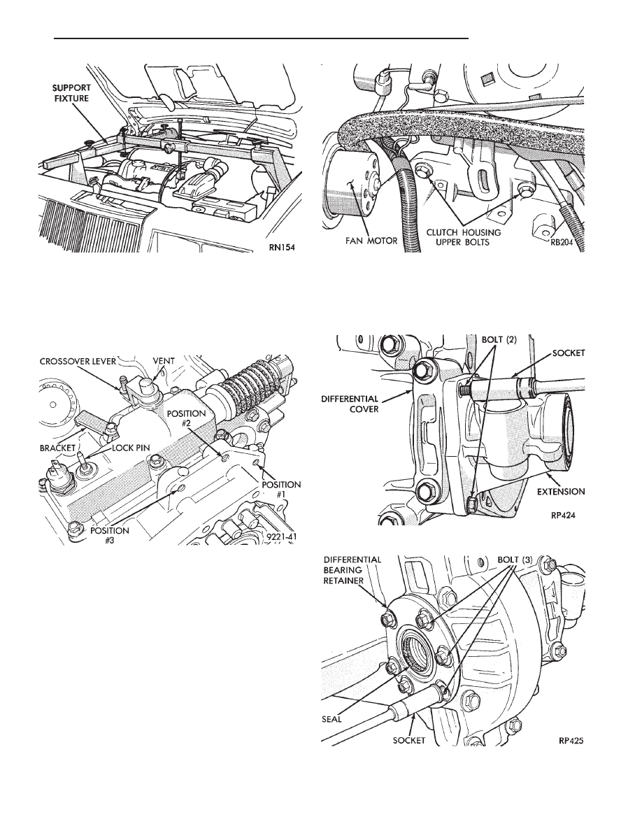
CAUTION: Bolts used for position number 1 and
number 3 are the same length. The bolt in the number
2 position is longer. If bolt number 2 is used in
position number 3 it can damage the selector shaft
housing when the bolt is seated (Fig. 12).
(7) Remove or install anti-rotational link (or anti-
hop damper) from crossmember bracket. Do not re-
move bracket from transaxle.
(8) Refer to Group 2 Suspension, to remove or
install both drive shafts.
When removing or installing the transaxle, it
may be helpful to use two locating pins in place
of the top two transaxle to engine block bolts
(Fig. 13).
Make the locating pins from two stock (transaxle
case to engine block) bolts as follows: Using a hacksaw,
remove bolt heads, cut slot in end of bolts for a screw
driver, and remove burrs with a grinding wheel. Install
the locating pins into the engine block and proceed
with transaxle installation. After transaxle is in place,
install bolts and remove locating pins before removing
transmission jack.
OUT OF CAR TRANSAXLE—DISASSEMBLE AND
ASSEMBLE
DIFFERENTIAL
Fig. 11 Engine Support Fixture
Fig. 12 Left Engine Mount Bolt Location
Fig. 13 Remove or Install Bolts
Fig. 1 Remove or Install 2 Extension Outer Bolts
Fig. 2 Remove or Install 3 Differential Bearing Re-
tainer Outer Bolts
.
TRANSAXLE
21 - 5