Chrysler Town & Country/Voyager, Dodge Caravan, Plymouth Voyager. Manual - part 62
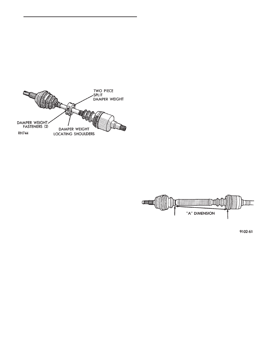
DAMPER WEIGHTS
Damper weights are used on the left driveshaft
assemblies of all front wheel drive vehicles (Fig. 1).
These weights are attached to the interconnecting
shaft and are available as a separate service part. They
should be removed from the driveshaft assembly dur-
ing driveshaft positioning specification procedures.
When the weights are attached between the locating
shoulders, tighten the fasteners to 28 N
Im (21 ft. lbs.)
torque.
DRIVESHAFT POSITIONING SPECIFICATIONS
Front wheel drive vehicles have engine mounts with
slotted holes allowing for side to side positioning of the
engine. If the vertical bolts on the right or left upper
engine mount have been loosened (e.g., engine removal
and installation) for any reason, or if the vehicle has
experienced
front
structural
damage,
driveshaft
lengths must be checked and corrected, if required. A
shorter than required driveshaft length can result in
objectionable noise. A longer than required driveshaft
length may result in potential damage.
Use of the following procedure will ensure satisfac-
tory driveshaft engagement under all normal vehicle
operating conditions.
(1) The vehicle must be completely assembled. Front
wheels must be properly aligned and in the straight
ahead position. The vehicle must be in a position so
that the full weight of the body is distributed to all four
tires. A platform hoist, or front end alignment rack, is
recommended.
(2) Using a tape measure or other suitable measur-
ing device. Measure the direct distance from the inner
edge of the outboard boot to the inner edge of the
inboard boot on both driveshafts. This measurement
must be taken at the bottom (six o’clock position) of the
driveshafts (Fig. 1).
Note that the required dimensions vary with drive-
shaft manufacturer.
(3) If the lengths of both shafts are within the range
specified, on the chart below, no further action is
required.
If either the left or right drive shaft length is not
within the specified range. Refer to Engine, Group 09,
Engine Removal and Installation to properly position
the engine according to the driveshaft lengths speci-
fied.
(4) If proper driveshaft lengths cannot be achieved
within the travel limits available in the slotted engine
mounts. Check for any condition that could effect the
side to side position of the measurement locations (e.g.,
engine support brackets, siderail alignment, etc.).
(5) After ensuring proper driveshaft lengths the
transmission shift linkage must be adjusted to ensure
proper operation. Refer to Transaxle, Group 21.
Fig. 1 Left Driveshaft with Damper Weight
Fig. 1 Driveshaft Positioning
.
FRONT SUSPENSION AND DRIVE SHAFTS
2 - 45