Chrysler Town & Country/Voyager, Dodge Caravan, Plymouth Voyager. Manual - part 57


  Index      Chrysler     Chrysler Town & Country/Voyager, Dodge Caravan, Plymouth Voyager - service repair manual 1992 year


Search            


Content   ..  55  56  57  58   ..


Chrysler Town & Country/Voyager, Dodge Caravan, Plymouth Voyager. Manual - part 57


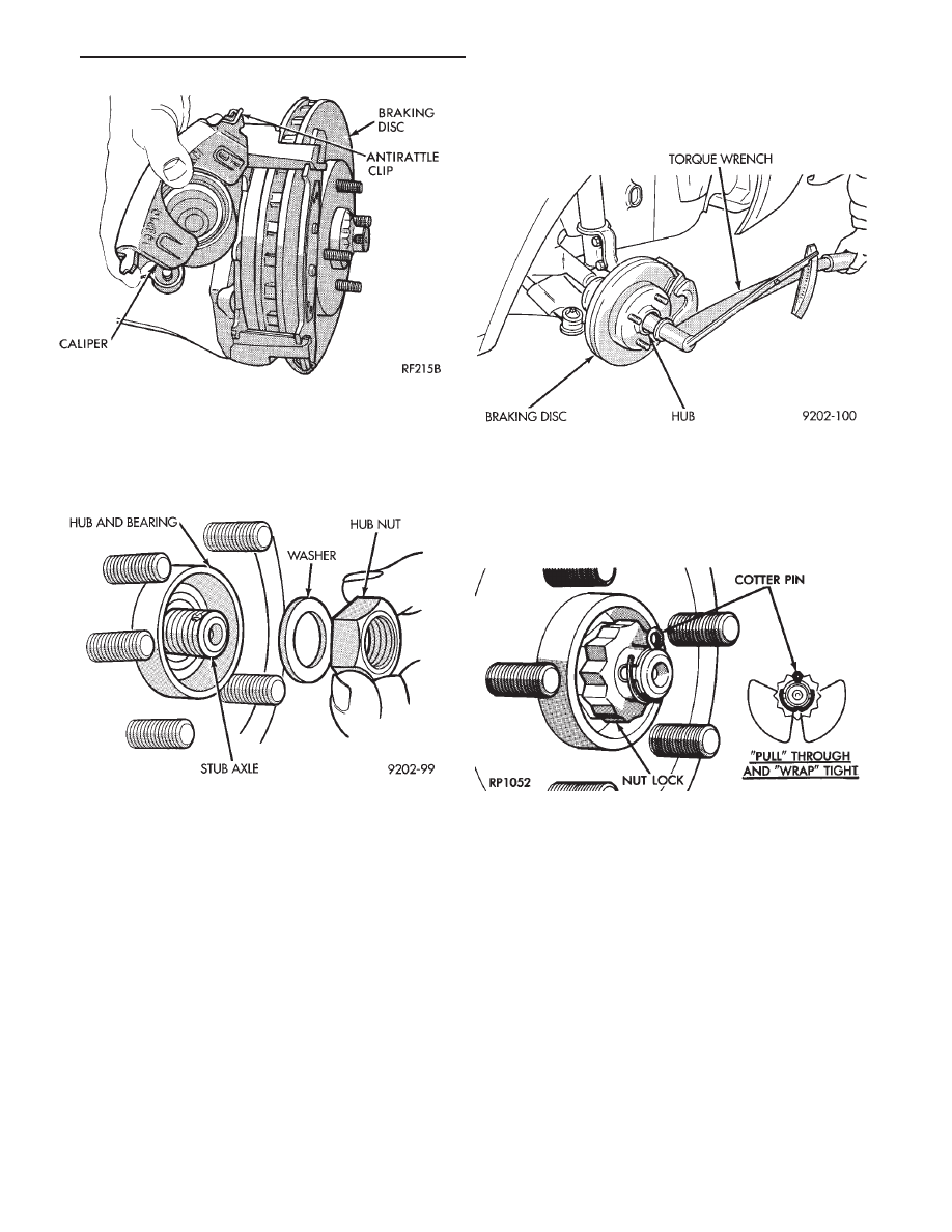
(11) Clean all foreign matter from the threads of the

stub axle (Fig. 17). Install the washer and hub nut (Fig.
17) onto the threads of the stub axle and tighten nut.

(12) With brakes applied, tighten front hub nut to

(244 N

Im) 180 ft. lbs. torque (Fig. 18).

(13) Install spring washer, nut lock, and new cotter

pin. Wrap cotter pin prongs tightly around nut lock
(Fig. 19).

Install wheel and tire assembly. Tighten wheel nuts

to 129 N

Im (95 ft. lbs.) torque.

Fig. 16 Installing Family Caliper

Fig. 17 Install Washer and Hub Nut

Fig. 18 Tighten Hub Nut

Fig. 19 Install Spring Washer, Nut Lock, & Cotter

Pin

.

FRONT SUSPENSION AND DRIVE SHAFTS

2 - 25

DRIVESHAFTS

INDEX

page

page

C/V Joint Boots

. . . . . . . . . . . . . . . . . . . . . . . . . . 40

Damper Weights

. . . . . . . . . . . . . . . . . . . . . . . . . 45

Driveshaft Identification

. . . . . . . . . . . . . . . . . . . . 26

Driveshaft Positioning Specifications

. . . . . . . . . . . 45

Driveshaft Reconditioning

. . . . . . . . . . . . . . . . . . . 31

Driveshaft Service Procedures

. . . . . . . . . . . . . . . 26

General Information

. . . . . . . . . . . . . . . . . . . . . . . 26

Inner C/V Joint

. . . . . . . . . . . . . . . . . . . . . . . . . . . 31

Outer C/V Joint

. . . . . . . . . . . . . . . . . . . . . . . . . . 35

GENERAL INFORMATION

All Chrysler front wheel drive vans and wagons use

only the unequal length driveshaft system.

The unequal length system has a short solid inter-

connecting shaft on the left side of the vehicle for all
engine transmission applications. On the right side of
the vehicle the interconnecting shafts very depending
on the transmission used in the vehicle. The manual
transmission equipped vehicles use a tubular shaft and
the automatic applications use a solid shaft (Fig. 1).

The driveshaft assemblies are three piece units.

Each driveshaft has a tripod joint, an interconnecting
shaft and a Rzeppa joint. The Tripod joint is splined
into the transaxle side gear and the Rzeppa joint has a
stub shaft that is splined into the wheel hub.

DRIVESHAFT IDENTIFICATION

Driveshafts used in front wheel van/wagon applica-

tions are identified by the driveshaft manufacturer.
Vehicles can be equipped with any of these driveshaft
assemblies. Each assembly can be identified as shown
in (Fig. 2).

DRIVESHAFT SERVICE PROCEDURES

Procedures for the removal and installation of the

driveshafts are essentially the same for all front wheel
drive vehicles. Each driveshaft has a spring within the
inboard tripod C/V joint that maintains constant en-
gagement with the transaxle. This allows transaxle to
be removed without dismantling part of the transaxle.

CAUTION: Boot sealing is vital to retain special lubri-
cants and to prevent foreign contaminants from en-
tering the C/V joint. Mishandling, such as allowing the
assemblies to dangle unsupported, pulling or push-
ing the ends can cut boots or damage C/V joints.
During removal and installation procedures always
support both ends of the driveshaft to prevent dam-
age.

Fig. 1 Front-Wheel-Drive - Driveshaft System

2 - 26

FRONT SUSPENSION AND DRIVE SHAFTS

.

HUB NUT AND HUB ASSEMBLY REMOVAL

Hub nut removal and installation is the same for all

front wheel drive vehicles. For removal and installa-
tion procedures see HUB NUT ASSEMBLIES IN-
STALL.

(1) Remove front stub axle cotter pin, nut lock and

spring washer (Fig. 1).

(2) Loosen front hub nut and wheel nuts while

vehicles is on floor and brakes applied (Fig. 2).

Fig. 2 Driveshaft Identification

Fig. 1 Remove Cotter Pin, Nut Lock, & Spring

Washer

Fig. 2 Loosen Hub Retaining Nut & Wheel Nuts

.

FRONT SUSPENSION AND DRIVE SHAFTS

2 - 27

(3) Raise vehicle, see Hoisting in Lubrication and

Maintenance, Group 0.

(4) Remove front hub nut and washer (Fig. 3).
(5) Remove the front wheel and tire assembly from

the vehicle.

DRIVESHAFT ASSEMBLIES

REMOVE

Inboard C/V joints have stub shafts splined into the

differential side gears. Driveshafts are retained in the
side gears by a constant force provided by a spring
contained within the inboard C/V joints.

(1) Before performing removal of the vehicles right

side driveshaft assembly. The speedometer pinion
must be removed from the transaxle assembly (Fig. 4).

(2) Remove clamp bolt securing ball joint stud into

steering knuckle (Fig. 5).

(3) Separate ball joint stud from steering knuckle by

prying against knuckle leg and control arm (Fig. 6).

CAUTION: Do not damage ball joint or C/V joint boots
(Fig. 6).

(4) Separate outer C/V joint splined shaft from hub

by holding C/V housing while moving knuckle (hub)
assembly away (Fig. 7).

CAUTION: Do not pry on or otherwise damage wear
sleeve on outer C/V joint.

(5) Support assembly at C/V joint housings. Remove

by pulling outward on the inner joint housing. DO
NOT PULL ON SHAFT 
(Fig. 8).

The driveshaft, when installed, acts as a bolt

and secures the hub/bearing assembly. If the
vehicle is to be supported or moved on its wheels.

Fig. 3 Remove Hub Nut & Washer

Fig. 5 Remove Ball Joint to Steering Knuckle Clamp

Bolt

Fig. 6 Separate Ball Joint from Knuckle

Fig. 4 Remove Speedometer Pinion (for Right Drive-

shaft)

2 - 28

FRONT SUSPENSION AND DRIVE SHAFTS

.


Content   ..  55  56  57  58   ..