Chrysler Town & Country/Voyager, Dodge Caravan, Plymouth Voyager. Manual - part 55
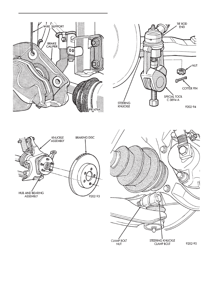
(6) Remove
the
braking
disc
from
the
front
hub/bearing assembly (Fig. 5).
(7) Remove the cotter pin and nut from the tie rod
end. Remove the tie rod end from the steering knuckle
arm using Puller, Special Tool C-3894-A (Fig. 6).
(8) Remove the clamp nut and bolt (Fig. 7) securing
the ball joint stud into the steering knuckle.
Fig. 4 Supporting Brake Caliper
Fig. 5 Remove or Install Braking Disc
Fig. 6 Disconnect Tie Rod End
Fig. 7 Remove or Install Steering Knuckle Clamp
Bolt
.
FRONT SUSPENSION AND DRIVE SHAFTS
2 - 17