Chrysler Town & Country/Voyager, Dodge Caravan, Plymouth Voyager. Manual - part 58


  Index      Chrysler     Chrysler Town & Country/Voyager, Dodge Caravan, Plymouth Voyager - service repair manual 1992 year


Search            


Content   ..  56  57  58  59   ..


Chrysler Town & Country/Voyager, Dodge Caravan, Plymouth Voyager. Manual - part 58


Install a bolt through the hub to ensure that the hub
bearing assembly cannot loosen.

INSTALL

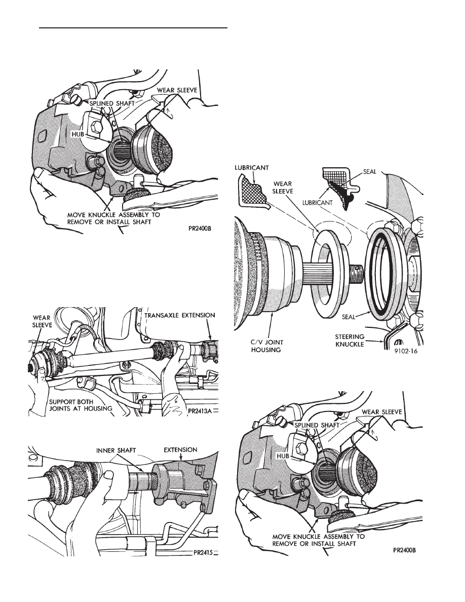
(1) Hold inner joint assembly at housing (Figs. 8 and

9) while aligning and guiding the inner joint spline into
the transaxle or intermediate shaft assembly.

CAUTION: Follow this Seal/Wear sleeve lubrication
during any service procedures where knuckle and
driveshaft are separated. Thoroughly clean seal and
wear sleeve with suitable solvent (solvent must not
touch boot) and lubricate both components prior to
installing driveshaft. Lubricate wear sleeve and seal
with Mopar

T

Multi-Purpose Lubricant, or equivalent.

Apply on the full circumference of the Wear Sleeve a bead

of lubricant that is 6 mm (1/4 in.) wide to seal contact area
(Fig. 10). Fill lip to housing cavity on Seal, complete circum-
ference, and wet seal lip with lubricant (Fig. 10).

(2) Push knuckle (hub) assembly out and install

splined outer C/V joint shaft in hub (Fig. 11).

Fig. 7 Separate Outer C/V Joint Shaft from Hub

Fig. 8 Removing Driveshaft Assembly Unequal

Length

Fig. 9 Installing Inner Shaft into Transaxle

Fig. 10 Seal & Wear Sleeve Lubrication

Fig. 11 Install Outer Shaft into Hub

.

FRONT SUSPENSION AND DRIVE SHAFTS

2 - 29

(3) Install steering knuckle assembly on ball joint

stud (Fig. 12).

CAUTION: Steering knuckle clamp bolt shown in
Figs. 12 and 13 is prevailing torque type, original or
equivalent bolt must be installed during assembly.

(4) Install and tighten clamp bolt to 136 N

Im (100 ft.

lbs.) torque (Fig. 13).

(5) Install speedometer pinion (Fig. 14).

(6) Fill differential with proper lubricant (see Lubri-

cation and Maintenance Group 0).

(7) Install front hub nut assembly.
(8) If after installing the driveshaft assembly, the

inboard boot appears collapsed or deformed. Vent the
inner boot by inserting, a round tipped small diameter
rod between the boot and shaft. If necessary, massage
the boot to remove all puckers being careful not to
allow dirt to enter or grease to leave the boot cavity. If
the boot is clamped to the shaft with a rubber garter
clamp, it need not be removed to perform this venting
operation. If the boot is clamped to the shaft using a
metal clamp, the clamp must be removed and dis-
carded before the rod can be inserted. After venting,
install a new Service Clamp, or equivalent using
special Tool C-4653 (see Boots Install section at the end
of this group for details).

HUB NUT ASSEMBLIES INSTALL

The front wheel hub nuts use a lock nut and cotter

pin to maintain proper wheel bearing preload and
prevent the nut from backing off. Install the assembly
as follows.

(1) Install washer and hub nut after cleaning any

foreign matter from stub axle threads (Fig. 15).

Fig. 12 Install Knuckle Assembly on Ball Joint Stud

Fig. 13 Tighten Clamp Bolt

Fig. 14 Install Speedometer Pinion

2 - 30

FRONT SUSPENSION AND DRIVE SHAFTS

.

(2) With brakes applied, tighten hub nut to 245 N

Im

(180 ft. lbs.) torque (Fig. 16).

(3) Install nut lock, spring washer and NEW cotter

pin. Wrap cotter pin prongs tightly around nut lock
(Fig. 17).

(4) Install wheel and tire assembly. Tighten wheel

nuts to 129 N

Im (95 ft. lbs.) torque (Fig. 18).

DRIVESHAFT RECONDITIONING

Driveshaft reconditioning and/or boot replacement

for all front wheel drive vehicles is essentially the same
per C/V joint.

Note that lubricant requirements and quanti-

ties are different for inner joints than for outer
joints, and type being serviced. Use only the
recommended lubricants.

Complete driveshaft components are shown in (Fig.

1).

Driveshaft requirements are different for vari-

ous vehicle models, engines, and transaxles, and
often change from one model year to the next.

Driveshaft parts will be different to accommo-

date this. Therefore, when replacing parts, be
sure to use only those specified in the service
parts catalog for the exact model year, model,
engine, transaxle, and type being serviced.

INNER C/V JOINT

DISASSEMBLE

With the driveshaft removed from the vehicle, iden-

tify the unit type (See Fig. 2 under Driveshafts Iden-
tification).

(1) Remove the boot clamps and pull back the boot to

gain access to the tripod retention system, which
prevents accidental separation from the C/V joint hous-
ing.

CAUTION: When removing the housing from the
tripod, hold the rollers in place on the trunnion studs
to prevent the rollers and needle bearings from falling
away. After the tripod is out of the housing secure the
rollers in place with tape (Fig. 4).

(2) Depending on the type of C/V joint assembly,

separate the C/V joint housing from the tripod as
follows:

Fig. 15 Install Washer and Hub Nut

Fig. 16 Tighten Hub Nut

Fig. 17 Install Spring Washer, Nut Lock, and New

Cotter Pin

Fig. 18 Install Wheel & Tire Assembly

.

FRONT SUSPENSION AND DRIVE SHAFTS

2 - 31

[S.S.G. Utilizes a wire ring tripod retainer which

expands into a groove around the top of the housing.
Use a flathead screwdriver to pry the wire ring out of
the groove and slide the tripod from the housing (Fig.
2). Do not mangle or destroy retainer during
disassembly.

G.K.N. The retention system on this assembly is

a integral part of the plastic collar on the inside
of the C/V joint housing. Clamp the stub shaft of
the C/V joint housing in a vise, use protective

caps on jaws of vise to prevent damage to stub
shaft. 
Hold the interconnecting shaft on an angle,
while gently pulling on the shaft until one of the tripod
bearings is free of the retaining collar. Continue hold-
ing the interconnecting shaft on an angle and gently
pull on the shaft until all rollers are free of the
retaining collar. See (Fig. 3).

TRIPOD ASSEMBLY REMOVAL FROM INTER-
CONNECTING SHAFT

S.S.G. AND G.K.N. WITH SINGLE RING TRIPOD RETEN-
TION.

Remove the tripod assembly to interconnecting shaft

retaining snap ring from the interconnecting shaft end
groove (Fig. 4). Remove the tripod assembly from the
interconnecting shaft by hand or by tapping the body of
the tripod assembly with a brass punch (Fig. 5).

Fig. 1 Driveshaft Components

Fig. 2 Separate Tripod From Housing S.S.G.

2 - 32

FRONT SUSPENSION AND DRIVE SHAFTS

.


Content   ..  56  57  58  59   ..