Chrysler Town & Country/Voyager, Dodge Caravan, Plymouth Voyager. Manual - part 41


  Index      Chrysler     Chrysler Town & Country/Voyager, Dodge Caravan, Plymouth Voyager - service repair manual 1992 year


Search            


Content   ..  39  40  41  42   ..


Chrysler Town & Country/Voyager, Dodge Caravan, Plymouth Voyager. Manual - part 41


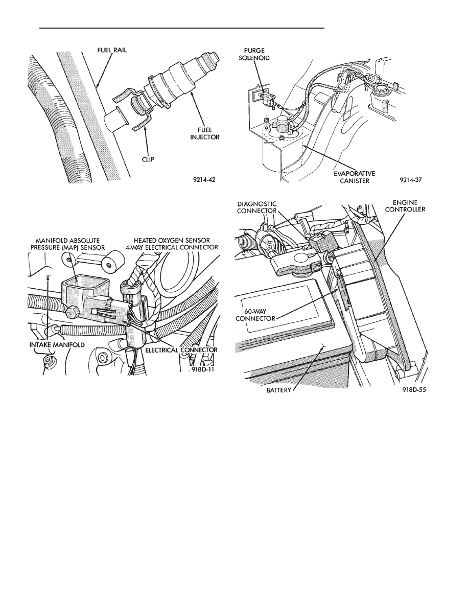
(2) Remove sensor by unscrewing from the intake

manifold (Fig. 20).

(3) Reverse the above procedure for installation.

CANISTER PURGE SOLENOID SERVICE

(1) Remove vacuum hose and electrical connector

from solenoid (Fig. 21).

(2) Depress tab on top of solenoid and slide the

solenoid downward out of mounting bracket.

(3) Reverse above procedure for installation.

ENGINE CONTROLLER SERVICE

(1) Remove air cleaner duct from engine controller.
(2) Remove battery.
(3) Remove engine controller mounting screws (Fig.

22).

(4) Remove 60-way electrical connector from engine

controller.

(5) Reverse the above procedure for installation.

CRANKSHAFT TIMING SENSOR

REMOVAL

(1) Disconnect crankshaft timing sensor electrical

connector from the wiring harness connector (Fig. 23).

(2) Remove crankshaft timing sensor retaining bolt.
(3) Pull crankshaft timing sensor straight up out of

the transaxle housing.

INSTALLATION

If the removed sensor is to be reinstalled, clean

off the old spacer on the sensor face. A NEW
SPACER must be attached to the sensor face
before installation. If the sensor is being re-
placed, confirm that the paper spacer is attached
to the face of the new sensor (Fig. 24).

(1) Install sensor in transaxle and push sensor down

until

contact

is

made

with

the

drive

plate.

Fig. 21 Canister Purge Solenoid

Fig. 19 Servicing Fuel Injector—Typical

Fig. 20 Manifold Absolute Pressure Sensor

Fig. 22 Engine Controller Removal

.

FUEL SYSTEM

14 - 111

While holding the sensor in this position, install and
tighten the retaining bolt to 11.9 N

Im (105 in. lbs.)

torque.

(2) Connect crankshaft timing sensor electrical con-

nector to the wiring harness connector.

CAMSHAFT SENSOR SERVICE

REMOVAL

(1) Disconnect camshaft reference sensor electrical

connector from the wiring harness connector (Fig. 25).

(2) Loosen camshaft timing sensor retaining bolt

enough to allow slot in sensor to slide past the bolt.

(3) Pull sensor up out of the chain case cover. Do not

pull on the sensor lead. There is an O-ring on the
sensor case. The O-ring may make removal difficult. A
light tap to top of sensor prior to removal may reduce
force needed for removal.

INSTALLATION

If the removed sensor is reinstalled, clean off

the old spacer on the sensor face. A NEW SPACER
must be attached to the face before installation.
Inspect O-ring for damage, replace if necessary.
If the sensor is being replaced, confirm that the
paper spacer is attached to the face and O-ring is
positioned in groove of the new sensor (Fig. 26).

(1) Apply a couple drops of clean engine oil to the

O-ring prior to installation. Install sensor in the chain

case cover and push sensor down until contact is made
with the cam timing gear. While holding the sensor in
this position, install and tighten the retaining bolt 11.9
N

Im (105 in. lbs.) torque.

(2) Connect camshaft reference sensor electrical con-

nector to harness connector. Position connector away
from the accessory belt.

HEATED OXYGEN SENSOR (O

2

SENSOR) SERVICE

The oxygen sensor is installed in the exhaust mani-

fold (Fig. 27).

CAUTION: Do not pull on the oxygen sensor wire
when disconnecting the electrical connector.

WARNING: THE EXHAUST MANIFOLD MAY BE EX-
TREMELY HOT. USE CARE WHEN SERVICING THE
OXYGEN SENSOR.

(1) Disconnect oxygen sensor electrical connector

(Fig. 28).

(2) Remove sensor using Tool C-4907 (Fig. 29).
When the sensor is removed, the exhaust manifold

threads must be cleaned with an 18 mm X 1.5 + 6E

Fig. 25 Camshaft Sensor

Fig. 23 Crankshaft Timing Sensor

Fig. 24 Crankshaft Sensor and Spacer

Fig. 26 Camshaft Sensor

14 - 112

FUEL SYSTEM

.

tap. If using original sensor, coat the threads with
Loctite 771-64 anti-seize compound or equivalent. New
sensors are packaged with compound on the threads
and no additional compound is required. The sensor
must be tightened to 27 N

Im (20 ft. lbs.) torque.

SPECIFICATIONS

Fig. 27 Oxygen Sensor—3.3L Engine

Fig. 28 Oxygen Sensor Connector

Fig. 29 Oxygen Sensor Socket

TEMPERATURE SENSOR SPECIFICATIONS

.

FUEL SYSTEM

14 - 113

TORQUE

14 - 114

FUEL SYSTEM

.


Content   ..  39  40  41  42   ..