Chrysler Town & Country/Voyager, Dodge Caravan, Plymouth Voyager. Manual - part 40


  Index      Chrysler     Chrysler Town & Country/Voyager, Dodge Caravan, Plymouth Voyager - service repair manual 1992 year


Search            


Content   ..  38  39  40  41   ..


Chrysler Town & Country/Voyager, Dodge Caravan, Plymouth Voyager. Manual - part 40


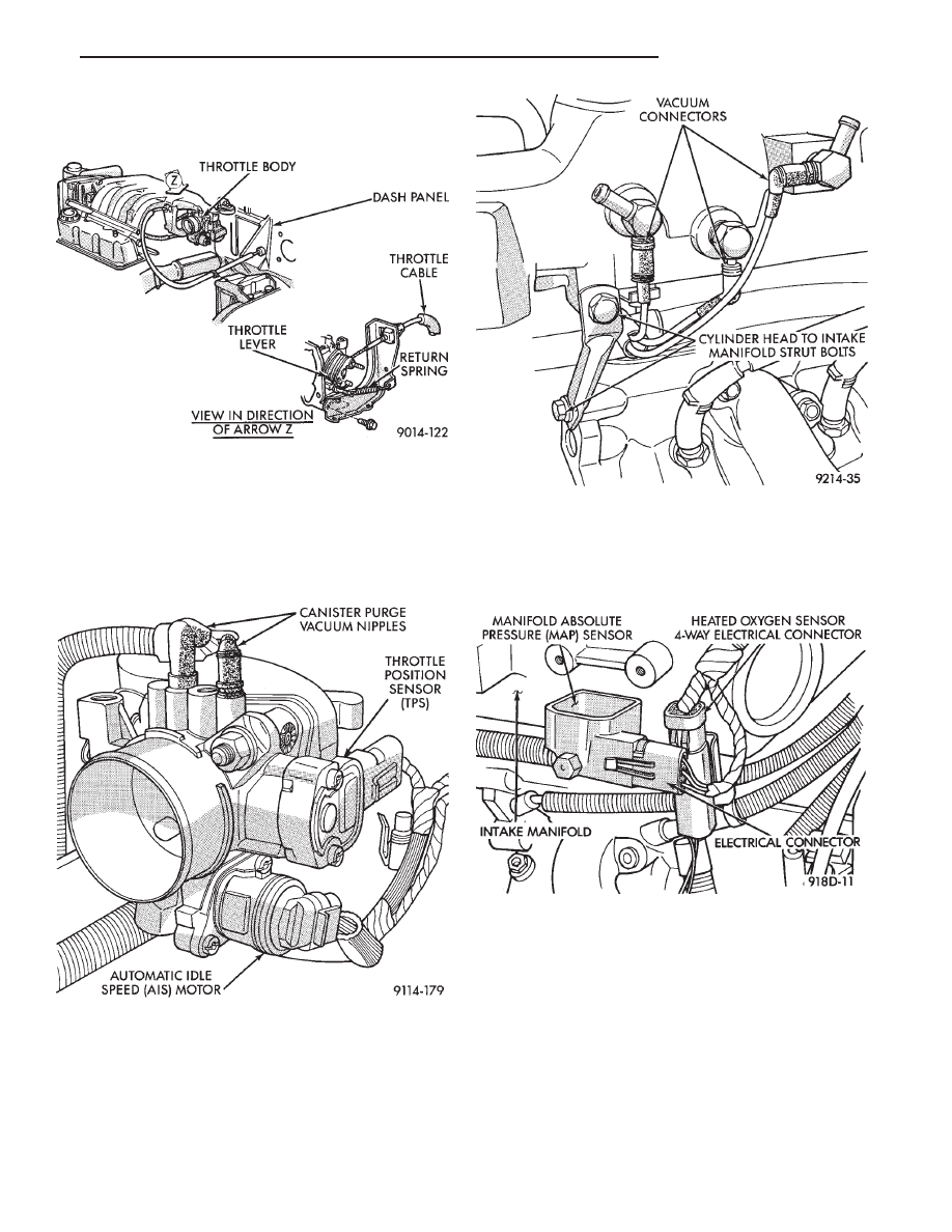
(4) Remove throttle cable (Fig. 6). Remove wiring

harness from throttle cable bracket and intake mani-
fold water tube.

(5) Disconnect automatic idles speed (AIS) motor

and throttle position sensor (TPS) electrical connectors
(Fig. 7). Refer to Automatic Idle Speed motor and
Throttle Position Sensor in this section.

(6) Remove vacuum hose harness from throttle body

(Fig. 7).

(7) Remove PCV and brake booster vacuum hoses

from air intake plenum.

(8) Remove vacuum harness connectors from intake

plenum (Fig. 8).

(9) Remove cylinder head to intake plenum strut

(Fig. 8).

(10) Disconnect electrical connectors from the MAP

sensor and heated oxygen sensor electrical connection.
Remove the engine mounted ground strap (Fig. 9).

(11) Remove the fuel hose quick connect fittings

from the chassis tubes. Refer to Fuel Hoses, Clamps
and Quick Connect Fittings in the Fuel Delivery
Section of this Group. 
Place a shop towel under the
connections to absorb any fuel spilled. fittings.

WARNING: WRAP A SHOP TOWEL AROUND HOSES
TO CATCH ANY GASOLINE SPILLAGE.

Fig. 6 Throttle Cable Attachment

Fig. 7 Electrical and Vacuum Connection to Throttle

Body

Fig. 8 Electrical and Vacuum Connections To Intake

Manifold

Fig. 9 MAP Sensor Electrical Connector

.

FUEL SYSTEM

14 - 107

(12) Remove direct ignition system (DIS) coils and

alternator bracket to intake manifold bolt (Fig. 10).

(13) Remove intake mounting manifold bolts and

rotate manifold back over rear valve cover (Fig. 11).

(14) Cover intake manifold with suitable cover when

servicing (Fig. 12).

(15) Remove vacuum harness connector from Fuel

Pressure Regulator.

(16) Remove fuel tube retainer bracket screw and

fuel rail attaching bolts (Fig. 12). Spread the retainer
bracket to allow fuel tube removal clearance.

(17) Remove fuel rail injector wiring clip from the

alternator bracket (Fig. 13).

(18) Disconnect cam sensor, coolant temperature

sensor, and engine temperature sensors (Fig. 13).

(19) Remove fuel rail. Be careful not to damage the

injector O-rings upon removal from their ports (Fig.
14).

INSTALLATION

(1) Ensure injector holes are clean. Replace O-rings

if damaged.

(2) Lube injector O-rings with a drop of clean engine

oil to ease installation.

(3) Put the tip of each injector into their ports. Push

the assembly into place until the injectors are seated in
the ports (Fig. 14).

(4) Install the fuel rail mounting bolts. Tighten bolts

to 22 N

Im (200 in. lbs.) torque (Fig. 12).

(5) Install fuel tube retaining bracket screw. Tighten

screw to 4 N

Im (35 in. lbs.) torque.

Fig. 10 Ignition Coils

Fig. 11 Intake Manifold Bolts

Fig. 12 Fuel Rail Attaching Bolts

Fig. 13 Fuel Injector Wiring Clip

14 - 108

FUEL SYSTEM

.

(6) Connect electrical connectors to cam sensor, cool-

ant temperature sensor and engine temperature sen-
sors.

(7) Install fuel injector harness wiring clips on the

alternator bracket and intake manifold water tube
(Fig. 13).

(8) Connect vacuum line to fuel pressure regulator.
(9) Remove covering on lower intake manifold and

clean surface.

(10) Place intake manifold gasket on lower manifold.

Put upper manifold into place and install bolts finger
tight.

(11) Install the alternator bracket to intake manifold

bolt and the cylinder head to intake manifold strut
bolts. (Do not tighten.)

(12) Following the tightening sequence in Figure 11,

tighten intake manifold bolts to 28 N

Im (250 in. lbs.)

torque.

(13) Tighten alternator bracket to intake manifold

bolt to 54 N

Im (40 ft. lbs.) torque.

(14) Tighten the cylinder head to intake manifold

strut bolts to 54 N

Im (40 ft. lbs.) torque (Fig. 8).

(15) Connect ground strap, MAP and heated oxygen

sensor electrical connectors.

(16) Connect vacuum harness to intake plenum.

Connect PCV system hoses.

(17) Clip wiring harness into the hole in the throttle

cable bracket.

(18) Connect electrical connectors to the throttle

position sensor (TPS) and Automatic Idle Speed (AIS)
motor.

(19) Connect vacuum harness to throttle body.
(20) Install the direct ignition system (DIS) coils.

Tighten fasteners to 12 N

Im (105 in. lbs.) torque.

(21) Install fuel hose quick connectors fittings to

chassis tubes. Refer to Fuel Hoses, Clamps and
Quick Connect Fittings in the Fuel Delivery Sec-
tion of this Group. 
Push the fittings onto the chassis
tubes until they click into place. Pull on the fittings to
ensure complete insertion. Fuel supply fitting is 5/16
inch and fuel return fitting is 1/4 inch.

(22) Install throttle cable.
(23) Install air cleaner and hose assembly.
(24) Connect negative cable to battery.

CAUTION: When using the ASD Fuel System Test, the
ASD relay and fuel pump relay remain energized for 7
minutes or until the test is stopped, or until the
ignition switch is turned to the Off position.

(25) With the ignition key in ON position, access the

DRB II ASD Fuel System Test to pressurize the fuel
system. Check for leaks.

FUEL PRESSURE REGULATOR

REMOVAL

(1) Perform fuel system pressure release procedure

before attempting any repairs. Refer to Fuel Pressure
Regulator Procedure in this section.

(2) Remove fuel pressure regulator vacuum connec-

tor. (Fig. 15).

(3) Remove regulator retainer screw (Fig. 15).
(4) Remove the fuel pressure regulator retainer (Fig.

15).

WARNING: PLACE A SHOP TOWEL UNDER FUEL
PRESSURE REGULATOR TO ABSORB ANY FUEL
SPILLAGE.

(5) Remove fuel pressure regulator and O-rings (Fig.

16).

Fig. 14 Fuel Rail Removal

Fig. 15 Fuel Pressure Regulator

.

FUEL SYSTEM

14 - 109

INSTALLATION

(1) Ensure fuel pressure regulator has two plastic

spacers (Fig. 16). Place O-rings in the fuel pressure
regulator cavity (Fig. 17). Do not install O-rings on the
fuel pressure regulator.

(2) Insert fuel pressure regulator into the fuel rail.
(3) Install fuel pressure regulator retainer (Fig. 15).
(4) Install retainer screw. Tighten to 7 N

Im (60 in.

lbs.) torque.

(5) Connect vacuum line to the fuel pressure regula-

tor.

CAUTION: When using the ASD Fuel System Test, the
ASD relay and fuel pump relay remain energized for 7
minutes or until the test is stopped, or until the
ignition switch is turned to the Off position.

(6) With the ignition key in ON position, access the

DRB II ASD Fuel System Test to pressurize the fuel
system. Check for leaks.

FUEL INJECTOR

The fuel rail must be removed first. Refer to Fuel

Injector Rail Assembly Removal in this section.

REMOVAL

(1) Disconnect injector wiring connector from injec-

tor.

(2) Position fuel rail assembly so that the fuel injec-

tors are easily accessible (Fig. 18).

(3) Rotate injector and pull injector out of fuel rail.

The clip will stay on the injector.

(4) Check injector O-ring for damage. If O-ring is

damaged, it must be replaced. If injector is reused, a
protective cap must be installed on the injector tip to
prevent damage. Replace the injector clip if it is dam-
aged.

(5) Repeat for remaining injectors.

INSTALLATION

(1) Before installing an injector the rubber O-ring

must be lubricated with a drop of clean engine oil to aid
in installation.

(2) Install injector clip by sliding open end into top

slot of the injector. The edge of the receiver cup will
slide into the side slots of clip (Fig. 19).

(3) Install injector top end into fuel rail receiver cap.

Be careful not to damage O-ring during installation
(Fig. 19).

(4) Repeat steps for remaining injectors.
(5) Connect fuel injector wiring.

MANIFOLD ABSOLUTE PRESSURE (MAP) SENSOR

(1) Disconnect electrical connector from MAP sensor.

Fig. 16 Fuel Pressure Regulator

Removal/Installation

Fig. 17 Fuel Pressure Regulator O-Rings

Fig. 18 Fuel Injector and Rail—Typical

14 - 110

FUEL SYSTEM

.


Content   ..  38  39  40  41   ..