Chrysler Town & Country/Voyager, Dodge Caravan, Plymouth Voyager. Manual - part 33


  Index      Chrysler     Chrysler Town & Country/Voyager, Dodge Caravan, Plymouth Voyager - service repair manual 1992 year


Search            


Content   ..  31  32  33  34   ..


Chrysler Town & Country/Voyager, Dodge Caravan, Plymouth Voyager. Manual - part 33


INSTALLATION

(1) Lubricate O-ring on fuel pressure regulator with

clean 30 weight engine oil.

(2) Install fuel pressure regulator into fuel rail.

Tighten screws to 10 N

Im (90 in. lbs.) torque.

(3) Install screw holding fuel return tube clamp in

place. Tighten screw to 10 N

Im (95 in. lbs.) torque.

(4) Connect vacuum hose to fuel pressure regulator.
(5) Connect fuel return hose to fuel return tube.

Tighten hose clamp to 1 N

Im ( 10 in. lbs.) torque.

(6) Connect negative battery cable.

CAUTION: When using the ASD Fuel System Test, the
ASD relay and fuel pump relay remain energized for 7
minutes or until the test is stopped, or until the
ignition switch is turned to the Off position.

(7) With the ignition key in ON position, access the

DRB II ASD Fuel System Test to pressurize the fuel
system. Check for leaks.

FUEL INJECTORS

WARNING: THE 3.0L MPI FUEL SYSTEM IS UNDER A
CONSTANT PRESSURE OF APPROXIMATELY 330
KPA (48 PSI). PERFORM FUEL PRESSURE RELEASE
PROCEDURE BEFORE SERVICING THE FUEL INJEC-
TORS.

REMOVAL

(1) Perform the Fuel Pressure Release Procedure.
(2) Disconnect negative cable from battery.
The fuel rail must be removed first to service the

injectors. Refer to Fuel Injector Rail Assembly Removal
in this section.

(3) Label each injector connector with its cylinder

number. Disconnect electrical connector from injector.

(4) Position fuel rail assembly so that the fuel injec-

tors are easily accessible.

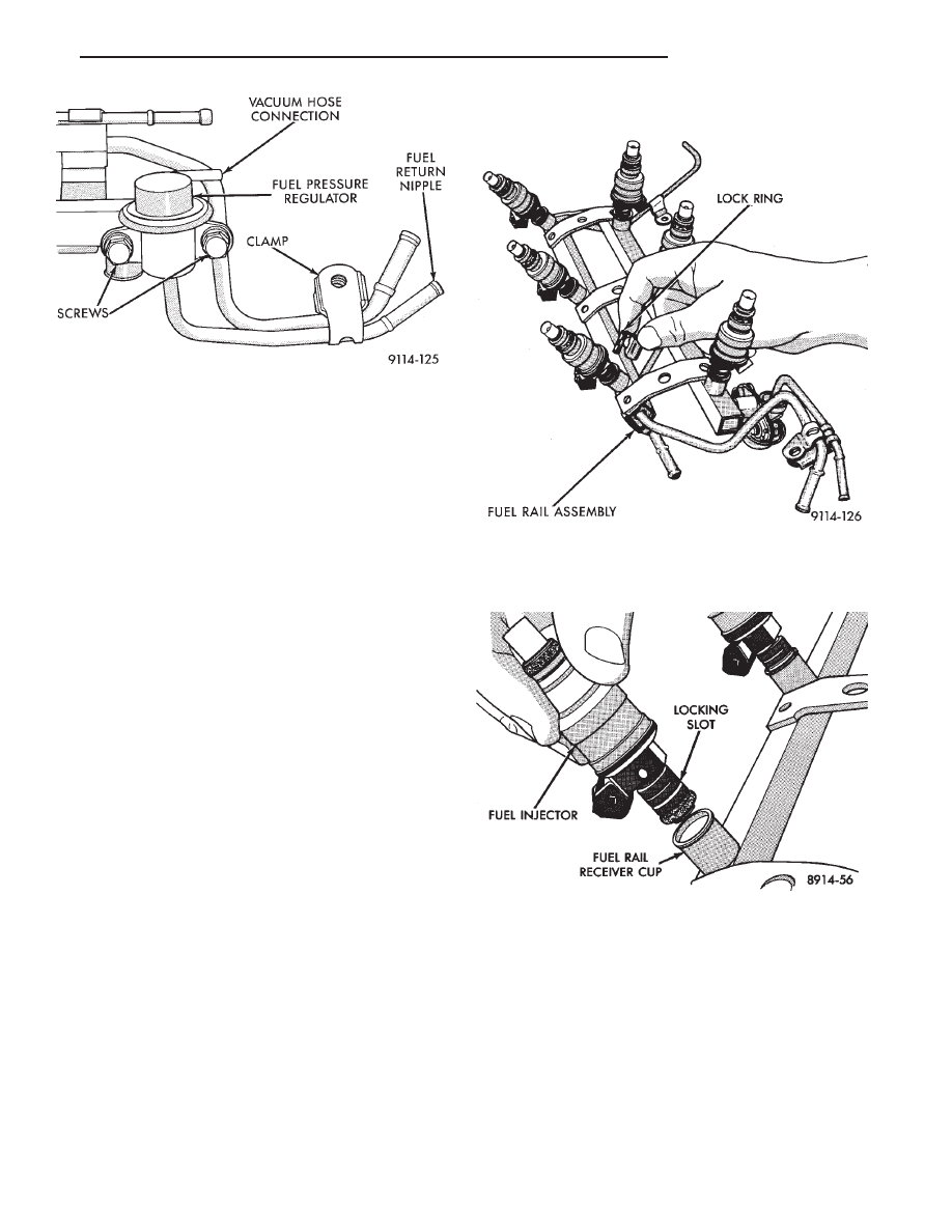
(5) Remove injector clip from fuel rail and injector

(Fig. 14).

(6) Pull injector straight out of fuel rail receiver cup

(Fig. 15).

(7) Check injector O-ring for damage. If O-ring is

damaged, it must be replaced. If injector is to be
reused, a protective cap must be installed on the
injector tip to prevent damage.

(8) Repeat procedure for remaining injectors.

INSTALLATION

(1) Before installing an injector, the rubber O-ring

must be lubricated with a drop of clean engine oil to aid
in installation.

Fig. 13 Fuel Pressure Regulator

Fig. 14 Fuel Injector and Rail

Fig. 15 Servicing Fuel Injector

.

FUEL SYSTEM

14 - 79

(2) Being careful not to damage O-ring, install injec-

tor nozzle end into fuel rail receiver cap (Fig. 15).

(3) Install injector clip by sliding open end into top

slot of the injector. The edge of the receiver cup will
slide into the side slots of clip (Fig. 15).

(4) Repeat steps for remaining injectors.
(5) Install fuel rail assembly. Refer to Fuel Rail

Assembly Installation in this section.

(6) Connect electrical connectors to injectors in cor-

rect order.

(7) Connect negative battery cable.

CAUTION: When using the ASD Fuel System Test, the
ASD relay and fuel pump relay remain energized for 7
minutes or until the test is stopped, or until the
ignition switch is turned to the Off position.

(8) With the ignition key in ON position, access the

DRB II ASD Fuel System Test to pressurize the fuel
system. Check for leaks.

MANIFOLD ABSOLUTE PRESSURE (MAP) SENSOR

(1) Remove vacuum hose and mounting screws from

manifold absolute pressure (MAP) sensor (Fig. 16).

(2) Disconnect electrical connector from sensor. Re-

move sensor.

(3) Reverse the above procedure for installation.

CANISTER PURGE SOLENOID SERVICE

(1) Remove vacuum hose and electrical connector

from solenoid (Fig. 17).

(2) Depress tab on top of solenoid and slide the

solenoid downward out of mounting bracket.

(3) Reverse above procedure to install.

ENGINE CONTROLLER

(1) Remove air cleaner duct from engine controller.
(2) Disconnect negative cable from battery. Discon-

nect positive cable from battery.

(3) Remove battery holddown. Remove battery.

(4) Remove engine controller mounting screws (Fig.

18).

(5) Remove the electrical connector from engine con-

troller. Remove engine controller.

(6) Reverse the above procedure for installation.

HEATED OXYGEN SENSOR (O

2

SENSOR)

The oxygen sensor is installed in the exhaust mani-

fold (Fig. 19).

CAUTION: Do not pull on the oxygen sensor wires
when disconnecting the electrical connector.

Fig. 16 Manifold Absolute Pressure Sensor

Fig. 17 Canister Purge Solenoid

Fig. 18 Engine Controller

14 - 80

FUEL SYSTEM

.

WARNING: THE EXHAUST MANIFOLD MAY BE EX-
TREMELY HOT. USE CARE WHEN SERVICING THE
OXYGEN SENSOR.

(1) Disconnect oxygen sensor electrical connector.

(2) Remove sensor using Tool C-4907 (Fig. 20).

When the sensor is removed, the exhaust manifold

threads must be cleaned with an 18 mm X 1.5 + 6E tap.
If using original sensor, coat the threads with Loctite
771-64 anti-seize compound or equivalent. New sen-
sors are packaged with compound on the threads and
no additional compound is required. The sensor must
be tightened to 27 N

Im (20 ft. lbs.) torque.

3.3L MULTI-POINT FUEL INJECTION—SYSTEM OPERATION

INDEX

page

page

Air Conditioning (A/C) Clutch Relay—Engine

Controller Output

. . . . . . . . . . . . . . . . . . . . . . . 87

Air Conditioning Switch Sense—Engine

Controller Input

. . . . . . . . . . . . . . . . . . . . . . . . . 83

Alternator Field—Engine Controller Output

. . . . . . 87

Auto Shutdown (ASD) Relay and Fuel Pump

Relay—Engine Controller Output

. . . . . . . . . . . . 88

Automatic Idle Speed (AIS) Motor—Engine

Controller Output . . . . . . . . . . . . . . . . . . . . . . . . 88

Battery Voltage—Engine Controller Input . . . . . . . . 83
Brake Switch—Engine Controller Input

. . . . . . . . . 83

Camshaft Sensor—Engine Controller Input

. . . . . . 84

Canister Purge Solenoid—Engine Controller

Output

. . . . . . . . . . . . . . . . . . . . . . . . . . . . . . . 88

Ccd Bus

. . . . . . . . . . . . . . . . . . . . . . . . . . . . . . . 82

Check Engine Lamp—Engine Controller Output

. . 89

Coolant Temperature Sensor—Engine

Controller Input

. . . . . . . . . . . . . . . . . . . . . . . . . 84

Crankshaft Sensor—Engine Controller Input

. . . . . 84

Diagnostic Connector—Engine Controller Output

. . 89

Electronic Automatic Transaxle Controller—Engine Con-

troller Output . . . . . . . . . . . . . . . . . . . . . . . . . . . 89

Emission Maintenance Reminder (EMR)

Lamp—Engine Controller Output

. . . . . . . . . . . . 89

Engine Controller

. . . . . . . . . . . . . . . . . . . . . . . . . 82

Engine Controller Reprogramming (Flash)

. . . . . . . 83

Fuel Injectors and Fuel Rail Assembly

. . . . . . . . . 92

Fuel Injectors—Engine Controller Output . . . . . . . . 89
Fuel Pressure Regulator . . . . . . . . . . . . . . . . . . . . 93
Fuel Supply Circuit

. . . . . . . . . . . . . . . . . . . . . . . . 92

General Information

. . . . . . . . . . . . . . . . . . . . . . . 81

Ignition Coil—Engine Controller Output

. . . . . . . . . 90

Manifold Absolute Pressure (MAP) Sensor—Engine

Controller Input

. . . . . . . . . . . . . . . . . . . . . . . . . 85

Modes of Operation

. . . . . . . . . . . . . . . . . . . . . . . 90

Oxygen Sensor (O

2

Sensor)—Engine Controller

Input

. . . . . . . . . . . . . . . . . . . . . . . . . . . . . . . . . 86

Radiator Fan Relay—Engine Controller Output

. . . 90

Speed Control Solenoids—Engine Controller

Output

. . . . . . . . . . . . . . . . . . . . . . . . . . . . . . . 90

Speed Control—Engine Controller Input

. . . . . . . . 86

Tachometer—Engine Controller Output

. . . . . . . . . 90

Throttle Body

. . . . . . . . . . . . . . . . . . . . . . . . . . . . 92

Throttle Position Sensor (TPS)—Engine

Controller Input

. . . . . . . . . . . . . . . . . . . . . . . . . 86

Transmission Park/Neutral Switch—Engine

Controller Input

. . . . . . . . . . . . . . . . . . . . . . . . . 86

Vehicle Distance (Speed) Sensor—Engine

Controller Input

. . . . . . . . . . . . . . . . . . . . . . . . . 87

GENERAL INFORMATION

The 3.3L engine uses a sequential Multi-point Elec-

tronic Fuel Injection system (Fig. 1). The MPI system is
computer regulated and provides precise air/fuel ratios
for all driving conditions.

The MPI system is operated by the Single Board

Engine Controller II (SBEC II), referred to in this
manual as the engine controller.

The engine controller regulates ignition timing, air-

fuel ratio, emission control devices, cooling fan, charg-
ing

system,

idle

speed

and

speed

control.

Fig. 19 Heated Oxygen Sensor

Fig. 20 Oxygen Sensor Socket

.

FUEL SYSTEM

14 - 81

Various sensors provide the inputs necessary for the
engine controller to correctly operate these systems. In
addition to the sensors, various switches also provide
inputs to the engine controller.

All inputs to the engine controller are converted into

signals. The engine controller can adapt its program-
ming to meet changing operating conditions.

Fuel is injected into the intake port above the intake

valve in precise metered amounts through electrically
operated injectors. The engine controller fires the in-
jectors in a specific sequence. The controller maintains
an air fuel ratio of 14.7 parts air to 1 part fuel by
constantly adjusting injector pulse width. Injector
pulse width is the length of time the injector is open.

The engine controller adjusts injector pulse width by

opening and closing the ground path to the injector.
Engine RPM (speed) and manifold absolute pressure
(air density) are the primary inputs that determine
injector pulse width.

SYSTEM DIAGNOSIS

The engine controller tests many of its own input and

output circuits. If a fault is found in a circuit, the
information is stored in the memory. Fault codes can
displayed using the Check Engine lamp. Also, the
technician can obtain the fault description by connect-
ing the DRB II to the vehicle.

CCD BUS

Various controllers and modules exchange informa-

tion through a communications port called the CCD
Bus. The engine controller transmits the check engine
lamp On/Off signal, engine RPM and vehicle load
information on the CCD Bus.

ENGINE CONTROLLER

The engine controller is a digital computer contain-

ing a microprocessor (Fig. 2). The controller receives
input signals from various switches and sensors that
are referred to as Engine Controller Inputs. Based on
these inputs, the controller adjusts various engine and
vehicle operations through devices that are referred to
as Engine Controller Outputs.

Engine Controller Inputs:

• Air Conditioning Controls

• Battery Voltage

• Brake Switch

• Camshaft Sensor

• Crankshaft Sensor

• Coolant Temperature Sensor

• Manifold Absolute Pressure (MAP) Sensor

• Oxygen Sensor

• SCI Receive

• Speed Control System Controls

• Throttle Position Sensor

Fig. 1 Multi-Point Fuel Injection Components

14 - 82

FUEL SYSTEM

.


Content   ..  31  32  33  34   ..