Chrysler Town & Country/Voyager, Dodge Caravan, Plymouth Voyager. Manual - part 31


  Index      Chrysler     Chrysler Town & Country/Voyager, Dodge Caravan, Plymouth Voyager - service repair manual 1992 year


Search            


Content   ..  29  30  31  32   ..


Chrysler Town & Country/Voyager, Dodge Caravan, Plymouth Voyager. Manual - part 31


STATE DISPLAY TEST MODE

The switch inputs used by the engine controller have

only two recognized states, HIGH and LOW. For this
reason, the engine controller cannot recognize the
difference between a selected switch position versus an
open circuit, a short circuit, or a defective switch. If the
change is displayed, it can be assumed that the entire
switch circuit to the engine controller is functional.
From the state display screen access either State
Display Inputs and Outputs or State Display Sensors.

STATE DISPLAY INPUTS AND OUTPUTS

Connect the DRB II tester to the vehicle. Access the

State Display screen. Then access Inputs and Outputs.
The following is a list of the engine control system
functions accessible through the Inputs and Outputs
screen.

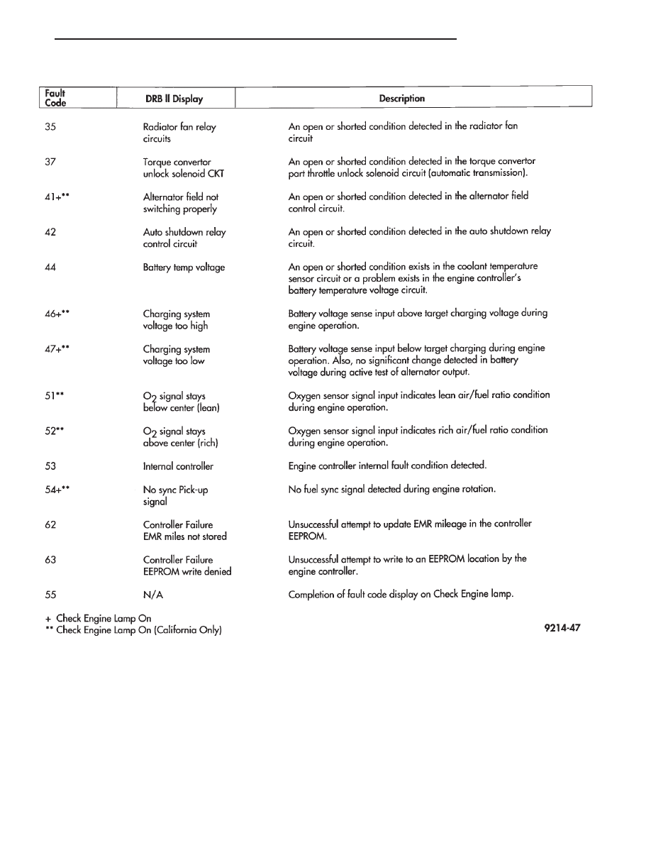
FAULT CODE DESCRIPTION (CON’T)

.

FUEL SYSTEM

14 - 71

Park/Neutral Switch
Speed Control Resume
Brake Switch
Speed Control On/Off
Speed Control Set
A/C Switch Sense
Z2 Voltage Sense
S/C Vent Solenoid
S/C Vacuum Solenoid
A/C Clutch Relay
EMR Lamp
EGR Solenoid
Auto Shutdown Relay
Radiator Fan Relay
Purge Solenoid
PTU Solenoid
Check Engine Lamp

STATE DISPLAY SENSORS

Connect the DRB II tester to the vehicle and access

the State Display screen. Then access Sensor Display.
The following is a list of the engine control system
functions accessible through the Sensor Display
screen:

Battery Temp Sensor
Oxygen Sensor Signal
Coolant Temperature
Coolant Temp Sensor
Throttle Position
Minimum Throttle
Battery Voltage
MAP Sensor Reading
AIS Motor Position
Adaptive Fuel Factor
Barometric Pressure
Min Airflow Idle Speed
Engine Speed
Fault #1 Key-On Info
Module Spark Advance
Speed Control Target
Fault #2 Key-on Info
Fault #3 Key-on Info
Speed Control Status
Speed Control Switch Voltage
Charging System Goal
Theft Alarm Status
Map Sensor Voltage
Vehicle Speed
Oxygen Sensor State
MAP Gauge Reading
Throttle Opening
Total Spark Advance

CIRCUIT ACTUATION TEST MODE

The circuit actuation test mode checks for proper

operation of output circuits or devices which the engine
controller cannot internally recognize. The engine con-
troller can attempt to activate these outputs and allow

an observer to verify proper operation. Most of the tests
provide an audible or visual indication of device opera-
tion (click of relay contacts, spray fuel, etc.). Except for
intermittent conditions, if a device functions properly
during testing, assume the device, its associated wir-
ing, and driver circuit working correctly.

OBTAINING CIRCUIT ACTUATION TEST

Connect the DRB II tester to the vehicle and access

the Actuators screen. The following is a list of the
engine control system functions accessible through
Actuators screens:

Stop All Tests
Ignition Coil #1
Fuel Injector #1
Fuel Injector #2
Fuel Injector #3
Fuel Injector #4
Fuel Injector #5
Fuel Injector #6
AIS Motor Open/Close
Radiator Fan Relay
A/C Clutch Relay
Auto Shutdown Relay
Fuel Pump Relay
Purge Solenoid
S/C Serv Solenoids
Alternator Field
All Solenoids/Relays
ASD Fuel System Test

THROTTLE BODY MINIMUM AIR FLOW CHECK
PROCEDURE

(1) Warm engine in Park or Neutral until the cooling

fan has cycled on and off at least once.

(2) Ensure that all accessories are off.
(3) Hook-up the timing check device and tachometer.
(4) Disconnect the coolant temperature sensor and

set basic timing to 12° BTDC

6 2° BTDC.

(5) Shut off engine. Reconnect coolant temperature

sensor wire.

(6) Disconnect the PCV valve hose from the PCV

valve (Fig. 21).

(7) Plug the PCV valve nipple.
(8) Disconnect the idle purge hose from the engine

vacuum harness tee (Fig. 22).

(9) Install Air Metering Fitting #6457 (0.125 inch

orifice) in the intake manifold mounted idle purge hose
(Fig. 23).

(10) Connect Diagnostic Readout Box II (DRB II).
(11) Restart the engine, allow engine to idle for at

least one minute.

(12) Using the DRBII, access Min. Airflow Idle

Speed.

(13) The following will then occur:

• AIS motor will fully close.

14 - 72

FUEL SYSTEM

.

• Idle spark advance will become fixed.

• Engine RPM will be displayed on Diagnostic Read-
out Box II (DRB II)

(14) Check idle RPM with tachometer, if idle RPM is

within the below specification then the throttle body
min. air flow is set correctly.

(15) If idle RPM is not within specifications, shut off

the engine and clean the throttle body as follows:

(a) Remove the throttle body from engine.

WARNING: CLEAN THROTTLE BODY IN A WELL
VENTILATED AREA. WEAR RUBBER OF BUTYL
GLOVES, DO NOT LET MOPAR PARTS CLEANER
COME IN CONTACT WITH EYES OR SKIN. AVOID
INGESTING THE CLEANER. WASH THOROUGHLY
AFTER USING CLEANER.

(b) While holding the throttle open, spray the

entire throttle body bore and the manifold side of the
throttle plate with Mopar Parts Cleaner. Only use
Mopar Parts Cleaner to clean the throttle body.

(c) Using a soft scuff pad, clean the top and bottom

of throttle body bore and the edges and manifold side
of the throttle blade. The edges of the throttle
blade and portions of the throttle bore that are
closest to the throttle blade when is closed,
must be free of deposits.

(d) Use compressed air to dry the throttle body.
(e) Inspect throttle body for foreign material.
(f) Install throttle body on manifold.
(g) Repeat steps 1 through 14. If the minimum air

flow is still not within specifications, the problem is
not caused by the throttle body.
(16) Shut off engine.
(17) Remove Air Metering Fitting #6457 from the

intake manifold idle purge hose. Reconnect the hose to
the engine vacuum harness tee.

(18) Remove the plug from the PCV valve. Reconnect

the PCV valve hose to the PCV valve.

(19) Disconnect the DRB II.

IGNITION TIMING PROCEDURE

Refer to Group 8D Ignition System.

60-WAY ENGINE CONTROLLER WIRING CONNEC-
TOR

Refer to the engine controller wiring connector dia-

gram (Fig. 24) for information regarding wire colors
and cavity numbers.

Fig. 21 3.0L PCV Valve

Fig. 22 3.0L Idle Purge Hose

Fig. 23 Air Metering Fitting 6457

IDLE SPECIFICATIONS

.

FUEL SYSTEM

14 - 73

Fig.

24

60—W

ay

Engine

Controller

W

iring

Connector—3.0L

Engine

14 - 74

FUEL SYSTEM

.


Content   ..  29  30  31  32   ..