Chrysler Town & Country/Voyager, Dodge Caravan, Plymouth Voyager. Manual - part 30


  Index      Chrysler     Chrysler Town & Country/Voyager, Dodge Caravan, Plymouth Voyager - service repair manual 1992 year


Search            


Content   ..  28  29  30  31   ..


Chrysler Town & Country/Voyager, Dodge Caravan, Plymouth Voyager. Manual - part 30


(22) Check engine harness to main harness electri-

cal connections.

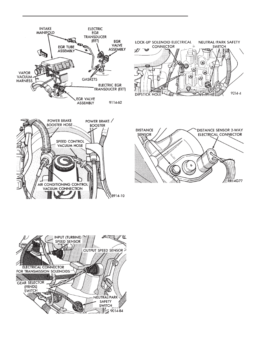
(23) Check all automatic transmission electrical con-

nections (Fig. 15 or 16).

(24) Check the vehicle distance sensor electrical

connection (Fig. 17).

(25) Inspect the engine controller 60-way electrical

connector for damage or spread terminals. Verify the
60-way connector is fully inserted into the socket of the
engine controller (Fig. 18). Ensure that wires are not
stretched or pulled out of the connector.

(26) Verify that all electrical connectors are fully

inserted into relays (Fig. 19 and Fig. 20).

(27) Check Battery Cable Connections.
(28) Check hose and wiring connections at fuel

pump. Check that wiring connector is making contact
with terminals on pump.

ON BOARD DIAGNOSTICS

The engine controller has been programmed to moni-

tor many different circuits of the fuel injection system.
If a problem is sensed with a monitored circuit often
enough to indicate an actual problem, the controller
stores a fault. If the problem is repaired or ceases to
exist, the engine controller cancels the Fault Code after
51 vehicle key on/off cycles.

Certain criteria must be met for a fault code to be

entered into engine controller memory. The criteria
may be a specific range of engine RPM, engine tem-
perature, and/or input voltage to the engine controller.

Fig. 15 Electronic Automatic Transmission Electrical

Connections

Fig. 13 EGR System Vacuum Hose Connections

Fig. 14 Power Brake Booster and Speed Control

Vacuum Hose Connections

Fig. 16 Automatic Transmission Electrical Connec-

tions

Fig. 17 Distance Sensor Electrical Connector

.

FUEL SYSTEM

14 - 67

It is possible that a fault code for a monitored circuit

may not be entered into memory even though a mal-
function has occurred. This may happen because one of
the fault code criteria for the circuit has not been met.
For example, assume that one of the fault code
criteria for the MAP sensor circuit is that the engine
must be operating between 750 and 2000 RPM to be
monitored for a fault code. If the MAP sensor output
circuit shorts to ground when engine RPM is above

2400 RPM (resulting in a 0 volt input to the engine
controller) a fault code will not be entered into memory.
This is because the condition does not occur within the
specified RPM range.

There are several operating conditions that the en-

gine controller does not monitor and set fault codes for.
Refer to Monitored Circuits and Non-Monitored Cir-
cuits in this section.

Stored fault codes can be displayed either by cycling

the ignition key On - Off - On - Off - On, or through use
of the Diagnostic Readout Box II (DRB II). The DRB II
connects to the diagnostic connector in the vehicle (Fig.
18).

MONITORED CIRCUITS

The engine controller can detect certain fault condi-

tions in the fuel injection system.

Open or Shorted Circuit - The engine controller

can determine if the sensor output (input to controller)
is within proper range. Also, the controller can deter-
mine if the circuit is open or shorted.

Output Device Current Flow - The engine control-

ler senses whether the output devices are hooked up. If
there is a problem with the circuit, the controller
senses whether the circuit is open, shorted to ground,
or shorted high.

Oxygen Sensor - The engine controller can deter-

mine if the oxygen sensor is switching between rich
and lean once the system has entered closed loop. Refer
to Modes of Operation in this section for an explanation
of closed loop operation.

NON-MONITORED CIRCUITS

The engine controller does not monitor the following

circuits, systems and conditions that could have mal-
functions that result in driveability problems. Fault
codes may not be displayed for these conditions. How-
ever, problems with these systems may cause fault
codes to be displayed for other systems.

Fig. 18 Engine Controller

Fig. 19 ASD, Fuel Pump, Radiator Fan and Starter

Relays

Fig. 20 A/C Clutch and A/C Fan Relays

14 - 68

FUEL SYSTEM

.

For example, a fuel pressure problem will not register
a fault directly, but could cause a rich or lean condition.
This could cause an oxygen sensor fault to be stored in
the engine controller.

Fuel Pressure - Fuel pressure is controlled by the

vacuum assisted fuel pressure regulator. The engine
controller cannot detect a clogged fuel pump inlet filter,
clogged in-line fuel filter, or a pinched fuel supply or
return line. However, these could result in a rich or
lean condition causing an oxygen sensor fault to be
stored in the engine controller.

Secondary Ignition Circuit - The engine control-

ler cannot detect an inoperative ignition coil, fouled or
worn spark plugs, ignition cross firing, or open spark
plug cables.

Engine Timing - The engine controller cannot de-

tect an incorrectly indexed timing chain, camshaft
sprocket and crankshaft sprocket. The engine control-
ler also cannot detect an incorrectly indexed distribu-
tor. However, these could result in a rich or lean
condition causing an oxygen sensor fault to be stored in
the engine controller.

Cylinder Compression - The engine controller

cannot detect uneven, low, or high engine cylinder
compression.

Exhaust System - The engine controller cannot

detect a plugged, restricted or leaking exhaust system.

Fuel Injector Malfunctions - The engine control-

ler cannot determine if the fuel injector is clogged, the
pintle is sticking or the wrong injector is installed.
However, these could result in a rich or lean condition
causing an oxygen sensor fault to be stored in the
engine controller.

Excessive Oil Consumption - Although the engine

controller monitors exhaust stream oxygen content
when the system is in closed loop, it cannot determine
excessive oil consumption.

Throttle Body Air Flow - The engine controller

cannot detect a clogged or restricted air cleaner inlet or
filter element.

Evaporative System - The engine controller will

not detect a restricted, plugged or loaded evaporative
purge canister.

Vacuum Assist - Leaks or restrictions in the

vacuum circuits of vacuum assisted engine control
system devices are not monitored by the engine con-
troller. However, these could result in a MAP sensor
fault being stored in the engine controller.

Engine Controller System Ground - The engine

controller cannot determine a poor system ground.
However, a fault code may be generated as a result of
this condition.

Engine Controller Connector Engagement - The

engine controller cannot determine spread or damaged
connector pins. However, a fault code may be generated
as a result of this condition.

HIGH AND LOW LIMITS

The engine controller compares input signal voltages

from each input device with established high and low
limits that are programmed into it for that device. If
the input voltage is not within specifications, and other
fault code criteria are met, a fault code will be stored in
memory. (Other fault code criteria might include en-
gine RPM limits or input voltages from other sensors or
switches that must be present before a fault condition
can be verified).

FAULT CODE DESCRIPTION

When a fault code appears, it indicates that the

Engine Controller has recognized an abnormal condi-
tion in the system. Fault codes can be obtained from
the Check Engine lamp on the Instrument Panel or
from the Diagnostic Readout Box II (DRBII). Fault
codes indicate the results of a failure but do not
identify the failed component directly.

SYSTEM TESTS

Apply parking brake and/or block wheels be-

fore performing idle check or adjustment, or any
engine running tests.

OBTAINING FAULT CODES

(1) Connect DRBII to the diagnostic connector lo-

cated in the engine compartment near the engine
controller.

(2) Start the engine if possible, cycle the transmis-

sion selector and the A/C switch if applicable. Shut off
the engine.

(3) Turn the ignition switch on, access Read Fault

Screen. Record all the fault messages shown on the
DRBII. Observe the check engine lamp on the instru-
ment panel. The lamp should light for 3 seconds then
go out (bulb check).

Fault code erasure; access erase fault code data

.

FUEL SYSTEM

14 - 69

FAULT CODE DESCRIPTION

14 - 70

FUEL SYSTEM

.


Content   ..  28  29  30  31   ..