Chevrolet Silverado / GMC Sierra. Manual - part 503
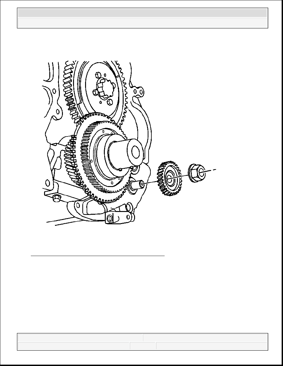
Fig. 315: View Of Oil Pump Driven Gear & Nut
Courtesy of GENERAL MOTORS CORP.
7. Install the oil pump driven gear.
2008 Chevrolet Silverado 1500
2008 ENGINE Engine Mechanical - 6.6L - Cab & Chassis Sierra, Cab & Chassis Silverado, Sierra & Silverado

Fig. 316: Removing/Installing Secondary Oil Pump Driven Gear Nut While Holding
Oil Pump Shaft
Courtesy of GENERAL MOTORS CORP.
8. While holding the secondary oil pump shaft with a hex driver, install the oil pump driven
gear nut.
Tighten: Tighten the nut to 100 N.m (74 lb ft).
2008 Chevrolet Silverado 1500
2008 ENGINE Engine Mechanical - 6.6L - Cab & Chassis Sierra, Cab & Chassis Silverado, Sierra & Silverado
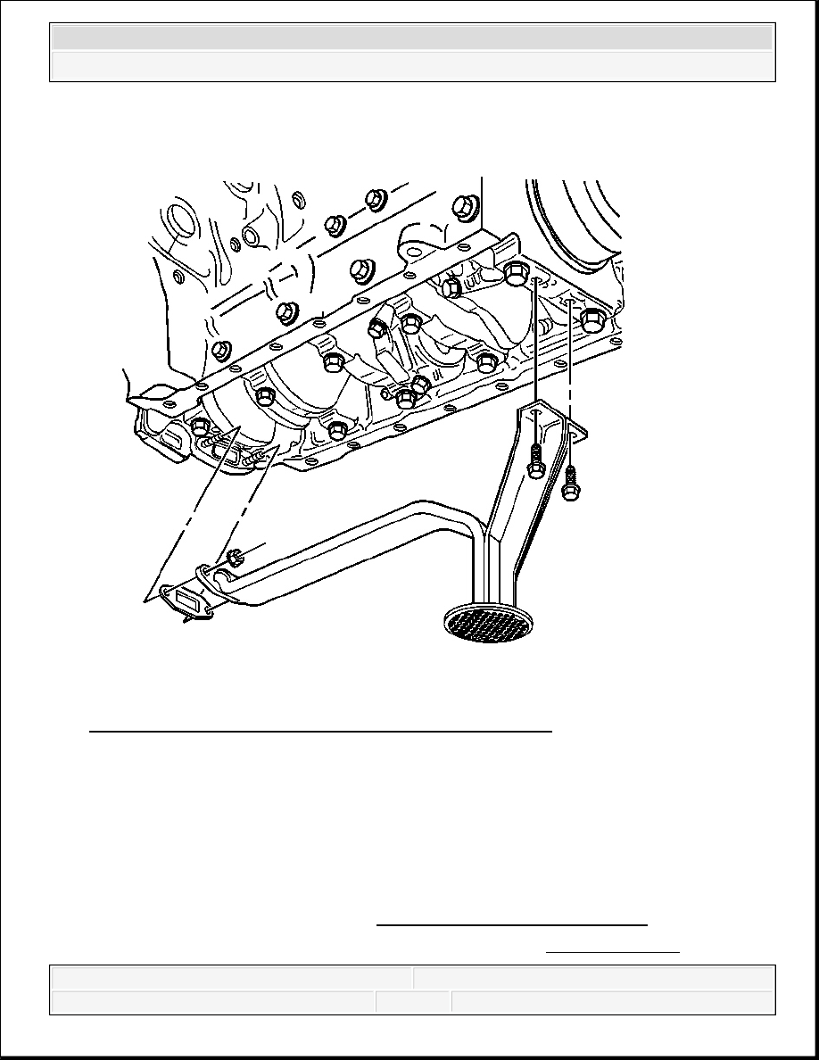
Fig. 317: View Of Oil Pump Screen, Bolts, Nuts & Gasket
Courtesy of GENERAL MOTORS CORP.
9. Install a NEW oil pump screen gasket to the oil pump.
10. Install the oil pump screen.
11. Install the oil pump screen bolts and nuts.
Tighten: Tighten the bolts/nuts to 25 N.m (18 lb ft).
12. Install the engine front cover. Refer to Engine Front Cover Replacement.
13. If the vehicle is a 2WD, install the flywheel housing. Refer to Engine Flywheel
2008 Chevrolet Silverado 1500
2008 ENGINE Engine Mechanical - 6.6L - Cab & Chassis Sierra, Cab & Chassis Silverado, Sierra & Silverado
Replacement.
14. Install the upper oil pan. Refer to Upper Oil Pan Replacement.
OIL FILTER ADAPTER AND OIL COOLER ASSEMBLY REPLACEMENT
Removal Procedure
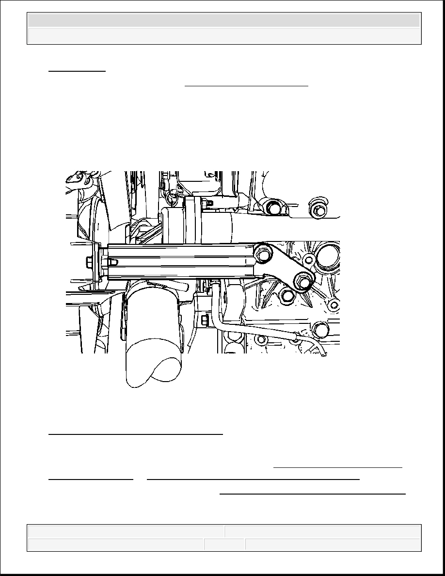
Fig. 318: View Of Charge Air Inlet Pipe
Courtesy of GENERAL MOTORS CORP.
1. Drain the engine coolant and the engine block. Refer to Cooling System Draining and
Filling (Vac-N-Fill) or Cooling System Draining and Filling (Static Fill) .
2. Remove the charge air inlet pipe. Refer to Charge Air Cooler Inlet Pipe Replacement .
3. Remove the cooling fan shroud bracket bolts (1).
4. Remove the cooling fan shroud bracket (2).
2008 Chevrolet Silverado 1500
2008 ENGINE Engine Mechanical - 6.6L - Cab & Chassis Sierra, Cab & Chassis Silverado, Sierra & Silverado