Chevrolet Silverado / GMC Sierra. Manual - part 499

Fig. 299: View Of Upper Oil Pan
Courtesy of GENERAL MOTORS CORP.
10. Remove the upper oil pan bolts and any brackets. Mark the bolt location of the bracket.
11. Separate the upper oil pan from the engine block using J 37228 . See Special Tools .
12. Remove the upper oil pan. The oil level indicator tube needs to be removed while lowering
the upper oil pan.
13. If required, clean and inspect the upper oil pan. Refer to Upper Oil Pan Cleaning and
Inspection .
Installation Procedure
2008 Chevrolet Silverado 1500
2008 ENGINE Engine Mechanical - 6.6L - Cab & Chassis Sierra, Cab & Chassis Silverado, Sierra & Silverado
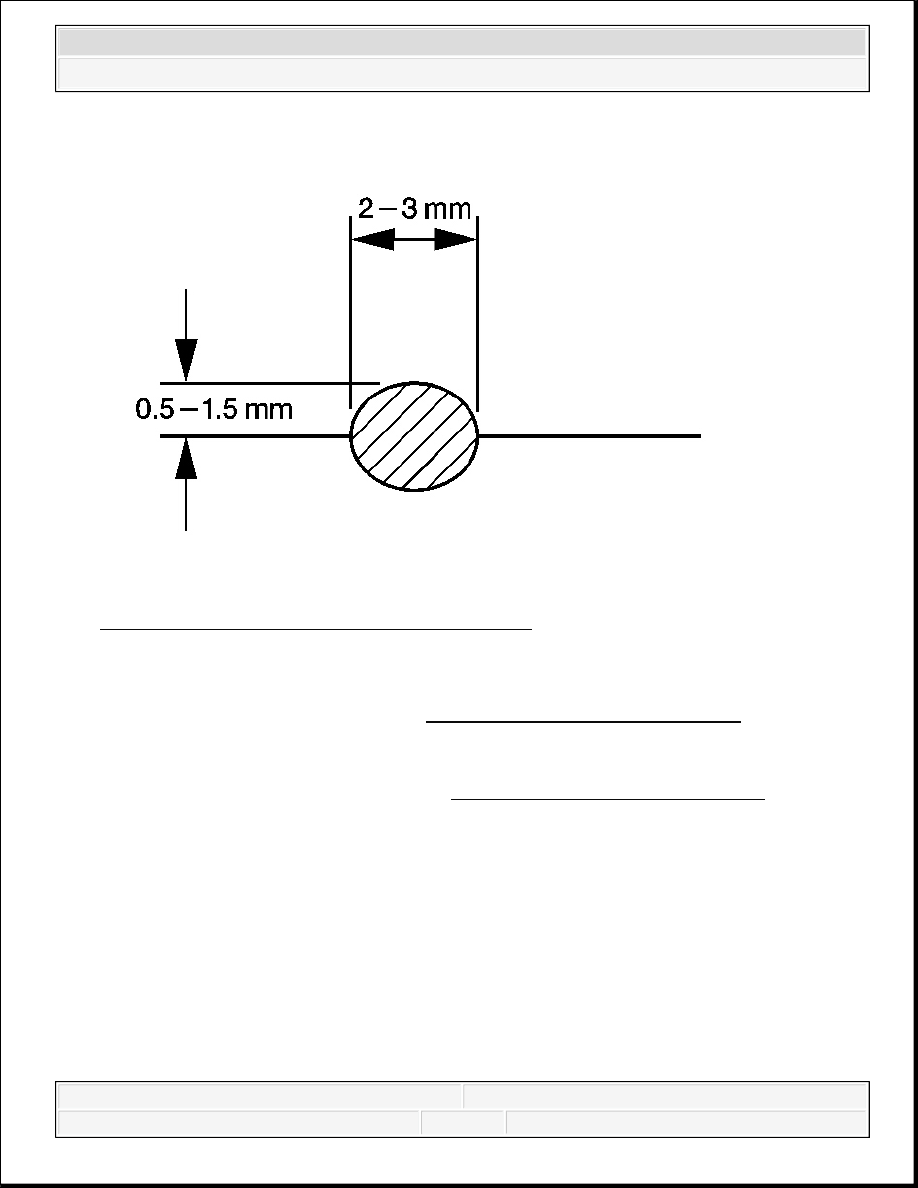
Fig. 300: Determining Sealant Bead Dimensions
Courtesy of GENERAL MOTORS CORP.
1. Apply a 2-3 mm (0.79-0.118 in) wide by 0.5-1.5 mm (0.02-0.06 in) bead of sealant to the
upper oil pan mating surfaces. Refer to Sealers, Adhesives, and Lubricants for the correct
part number.
2. Apply a 2-3 mm (0.79-0.118 in) wide by 0.5-1.5 mm (0.02-0.06 in) bead of sealant to the
flywheel housing sealing surface. Refer to Sealers, Adhesives, and Lubricants for the
correct part number.
2008 Chevrolet Silverado 1500
2008 ENGINE Engine Mechanical - 6.6L - Cab & Chassis Sierra, Cab & Chassis Silverado, Sierra & Silverado
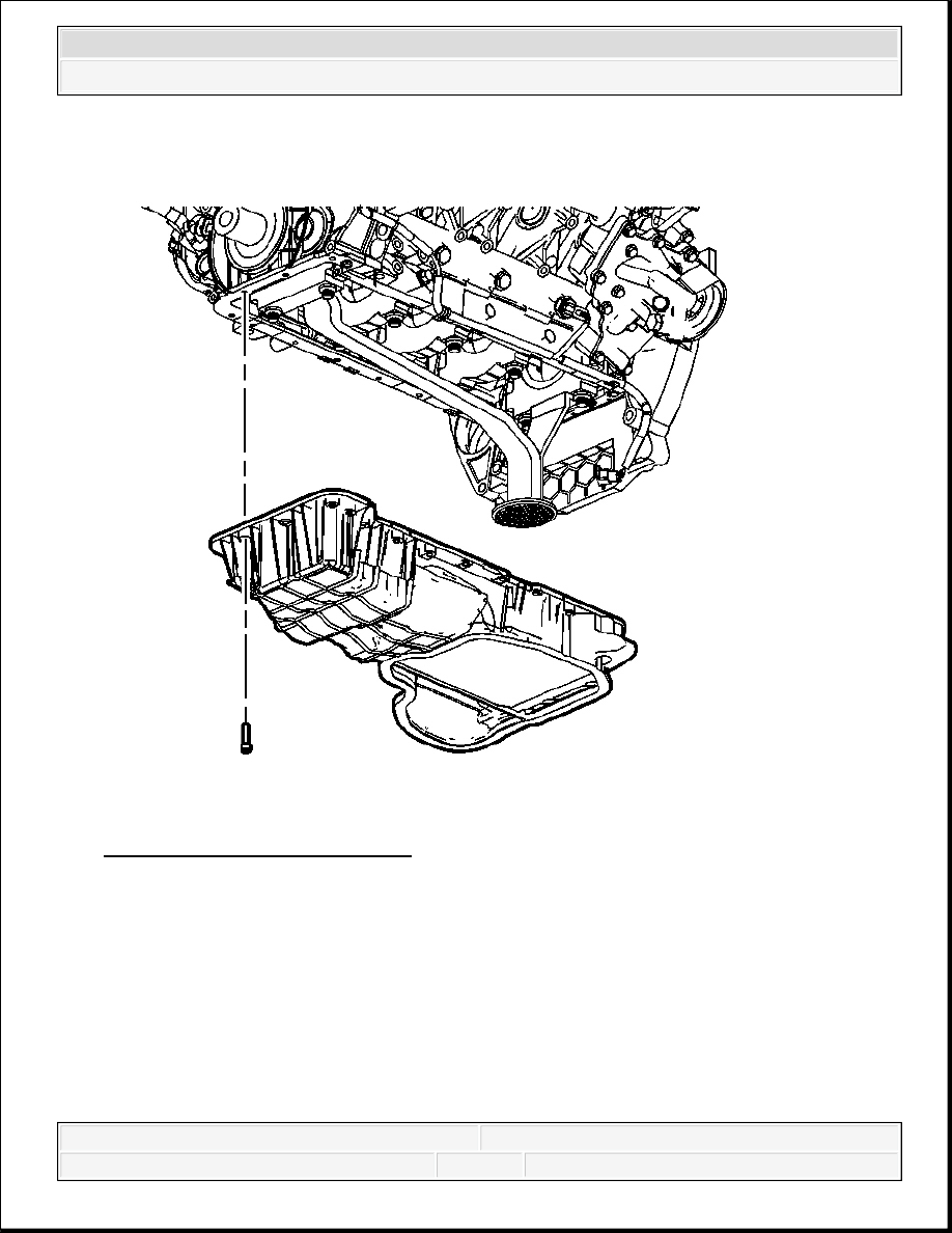
Fig. 301: View Of Upper Oil Pan
Courtesy of GENERAL MOTORS CORP.
3. Install the upper oil pan to the engine block. Ensure the oil level indicator tube is installed
into the upper oil pan.
2008 Chevrolet Silverado 1500
2008 ENGINE Engine Mechanical - 6.6L - Cab & Chassis Sierra, Cab & Chassis Silverado, Sierra & Silverado

Fig. 302: Upper Oil Pan Bolts Tightening Sequence
Courtesy of GENERAL MOTORS CORP.
4. Install any brackets and the upper oil pan bolts in the sequence shown.
Tighten: Tighten the bolts to 20 N.m (15 lb ft).
NOTE:
Refer to Fastener Notice .
2008 Chevrolet Silverado 1500
2008 ENGINE Engine Mechanical - 6.6L - Cab & Chassis Sierra, Cab & Chassis Silverado, Sierra & Silverado