Chevrolet Silverado / GMC Sierra. Manual - part 437
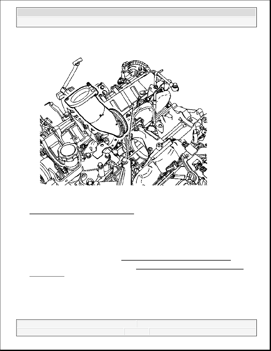
Fig. 76: View Of Intake Manifold Tube
Courtesy of GENERAL MOTORS CORP.
7. Install 2 NEW O-rings onto the intake manifold tube.
8. Lubricate the O-rings with clean engine oil to aid in the installation.
9. Install the intake manifold tube.
10. Install the water outlet tube. Refer to Water Outlet Tube Replacement (LMM) .
11. Install the EGR valve cooler tube. Refer to Exhaust Gas Recirculation Valve Cooler
Replacement .
INTAKE MANIFOLD REPLACEMENT - LEFT SIDE
Removal Procedure
2008 Chevrolet Silverado 1500
2008 ENGINE Engine Mechanical - 6.6L - Cab & Chassis Sierra, Cab & Chassis Silverado, Sierra & Silverado

Fig. 77: View Of Intake Manifold (Right)
Courtesy of GENERAL MOTORS CORP.
1. Remove the center intake manifold. Refer to Center Intake Manifold Replacement.
2. Remove the right fuel rail. Refer to Fuel Rail Fuel Feed Pipe Replacement - Right
Side .
3. Remove the intake manifold bolts/nuts.
4. Remove the intake manifold.
IMPORTANT: The intake manifold uses sealer. Pry at the area by the fuel
rail bolt holes in order to avoid damage to the sealing
surfaces.
2008 Chevrolet Silverado 1500
2008 ENGINE Engine Mechanical - 6.6L - Cab & Chassis Sierra, Cab & Chassis Silverado, Sierra & Silverado
5. To prevent entry of debris in the cylinder head tape the openings.
6. If required, clean and inspect the intake manifold. Refer to Intake Manifold Cleaning and
Inspection .
Installation Procedure
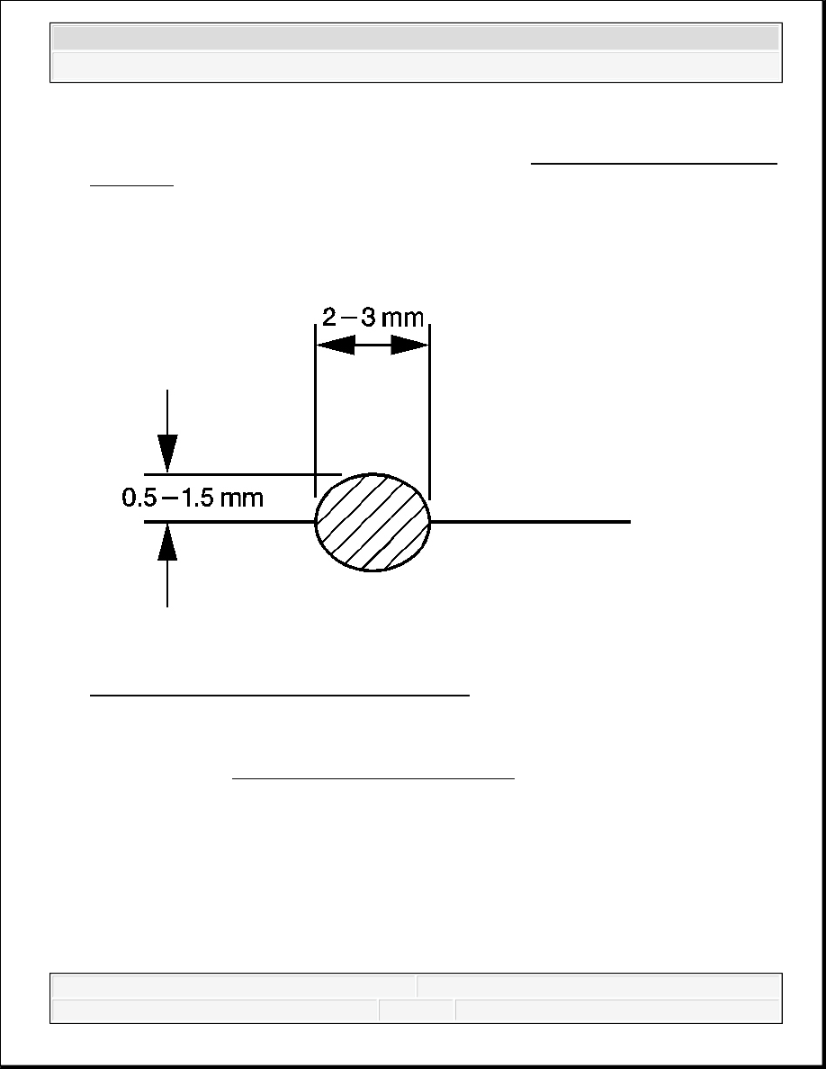
Fig. 78: Determining Sealant Bead Dimensions
Courtesy of GENERAL MOTORS CORP.
1. Apply a 2-3 mm (1/8 in) wide, by 0.5-1.5 mm (1/16 in) high bead of sealant to the intake
manifold. Refer to Sealers, Adhesives, and Lubricants for the correct part number.
2008 Chevrolet Silverado 1500
2008 ENGINE Engine Mechanical - 6.6L - Cab & Chassis Sierra, Cab & Chassis Silverado, Sierra & Silverado

Fig. 79: View Of Intake Manifold (Right)
Courtesy of GENERAL MOTORS CORP.
2. Install the intake manifold.
3. Install the intake manifold bolts/nuts.
2008 Chevrolet Silverado 1500
2008 ENGINE Engine Mechanical - 6.6L - Cab & Chassis Sierra, Cab & Chassis Silverado, Sierra & Silverado