Chevrolet Silverado / GMC Sierra. Manual - part 435
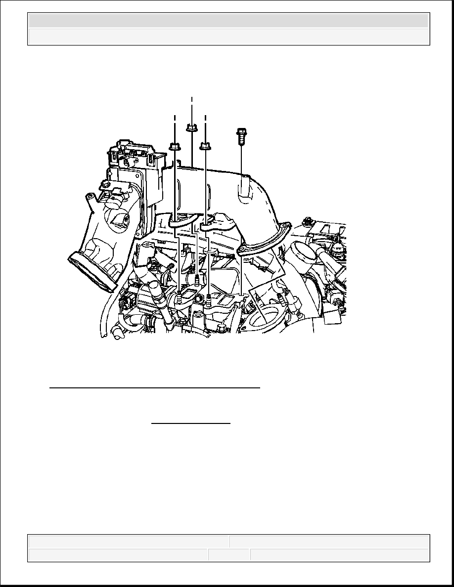
Fig. 68: View Of Air Inlet Tube & Components
Courtesy of GENERAL MOTORS CORP.
3. Install the air inlet tube and NEW gaskets.
4. Install the air inlet tube nuts and bolt.
Tighten: Tighten the nuts to 25 N.m (18 lb ft).
5. Connect the intake air heater electrical connector.
6. Connect the MAP sensor electrical connector.
7. Install the engine harness clip to the air inlet tube.
NOTE:
Refer to Fastener Notice .
2008 Chevrolet Silverado 1500
2008 ENGINE Engine Mechanical - 6.6L - Cab & Chassis Sierra, Cab & Chassis Silverado, Sierra & Silverado

Fig. 69: View Of Air Inlet Tube To Intake Manifold Tube Bolt & Nut
Courtesy of GENERAL MOTORS CORP.
8. Install the air inlet tube to intake manifold tube bolt and nut.
Tighten: Tighten the bolt/nut to 10 N.m (89 lb in).
2008 Chevrolet Silverado 1500
2008 ENGINE Engine Mechanical - 6.6L - Cab & Chassis Sierra, Cab & Chassis Silverado, Sierra & Silverado

Fig. 70: View Of Electrical Harness Bolts
Courtesy of GENERAL MOTORS CORP.
9. Install the electrical harness bolts (1).
Tighten: Tighten the bolts to 4 N.m (35 lb in).
10. Install the intake air valve. Refer to Intake Air Valve Replacement .
CENTER INTAKE MANIFOLD REPLACEMENT
Removal Procedure
2008 Chevrolet Silverado 1500
2008 ENGINE Engine Mechanical - 6.6L - Cab & Chassis Sierra, Cab & Chassis Silverado, Sierra & Silverado

Fig. 71: View Of Intake Manifold Tube
Courtesy of GENERAL MOTORS CORP.
1. Remove the exhaust gas recirculation (EGR) valve cooler tube. Refer to Exhaust Gas
Recirculation Valve Cooler Replacement .
2. Remove the water outlet tube. Refer to Water Outlet Tube Replacement (LMM) .
3. Remove the intake manifold tube.
4. Remove and discard the 2 intake manifold tube gaskets.
5. Remove the turbocharger. Refer to Turbocharger Replacement.
2008 Chevrolet Silverado 1500
2008 ENGINE Engine Mechanical - 6.6L - Cab & Chassis Sierra, Cab & Chassis Silverado, Sierra & Silverado