Chevrolet Silverado / GMC Sierra. Manual - part 434
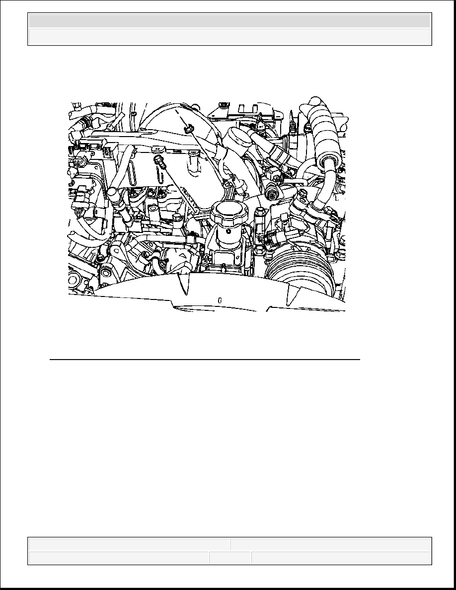
Fig. 64: View Of Air Inlet Tube To Intake Manifold Tube Bolt & Nut
Courtesy of GENERAL MOTORS CORP.
4. Remove the air inlet tube to intake manifold tube bolt and nut.
2008 Chevrolet Silverado 1500
2008 ENGINE Engine Mechanical - 6.6L - Cab & Chassis Sierra, Cab & Chassis Silverado, Sierra & Silverado
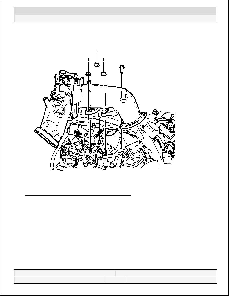
Fig. 65: View Of Air Inlet Tube & Components
Courtesy of GENERAL MOTORS CORP.
5. Disconnect the intake air heater electrical connector.
6. Disconnect the manifold absolute pressure (MAP) sensor electrical connector.
7. Remove the engine harness clip from the air inlet tube.
8. Remove the air inlet tube nuts and bolt.
9. Remove the air inlet tube.
2008 Chevrolet Silverado 1500
2008 ENGINE Engine Mechanical - 6.6L - Cab & Chassis Sierra, Cab & Chassis Silverado, Sierra & Silverado
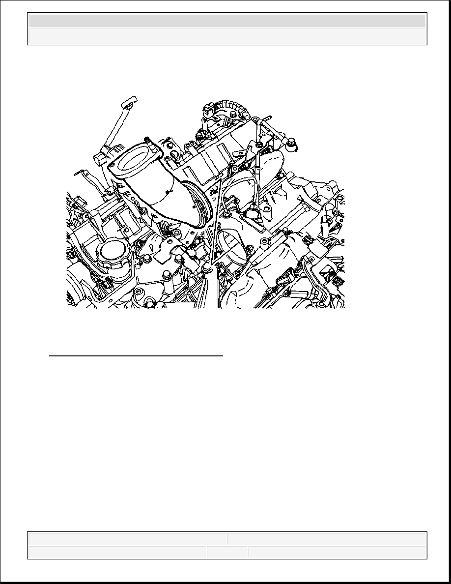
Fig. 66: View Of Intake Manifold Tube
Courtesy of GENERAL MOTORS CORP.
10. If necessary, remove the intake manifold tube.
11. If necessary, remove and discard the 2 O-ring seals from the tube.
12. Clean the gasket surfaces of the exhaust gas recirculation (EGR) cooler tube, intake
manifold tube and inlet tube.
Installation Procedure
2008 Chevrolet Silverado 1500
2008 ENGINE Engine Mechanical - 6.6L - Cab & Chassis Sierra, Cab & Chassis Silverado, Sierra & Silverado

Fig. 67: View Of Intake Manifold Tube
Courtesy of GENERAL MOTORS CORP.
1. If necessary, install NEW O-ring seals onto the tube.
2. If necessary, install the intake manifold tube.
2008 Chevrolet Silverado 1500
2008 ENGINE Engine Mechanical - 6.6L - Cab & Chassis Sierra, Cab & Chassis Silverado, Sierra & Silverado