Content .. 2282 2283 2284 2285 ..
Chevrolet Silverado / GMC Sierra. Manual - part 2284
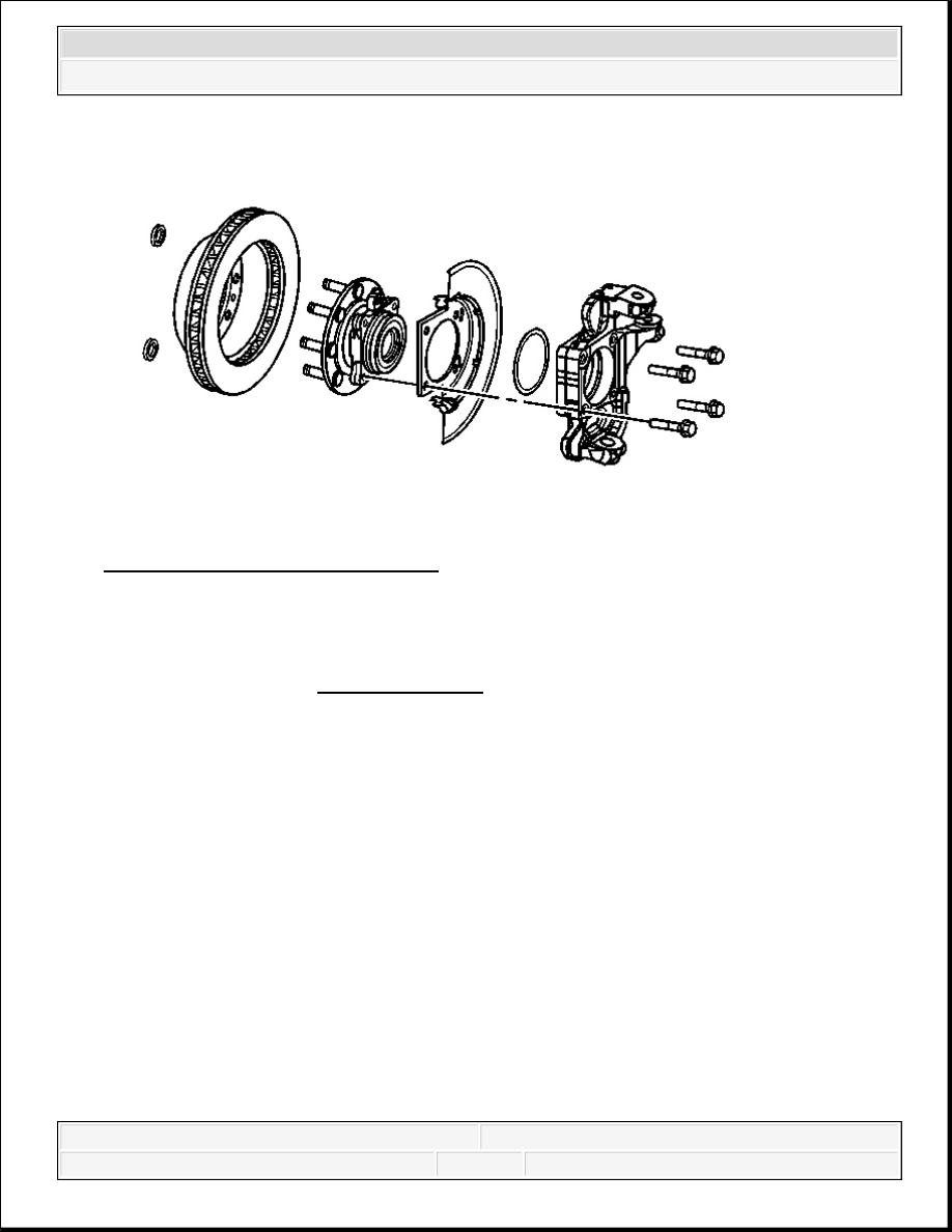
Fig. 34: Splash Shield (25/35 Series)
Courtesy of GENERAL MOTORS CORP.
3. Install the O-ring to the steering knuckle.
4. Install the wheel speed sensor to the wheel hub and bearing.
Tighten: Tighten the sensor mounting bolt to 18 N.m (13 lb ft).
5. Install the wheel hub and bearing and splash shield to the vehicle.
6. Install the wheel hub and bearing mounting bolts.
Tighten: Tighten the wheel hub to knuckle bolts to 180 N.m (133 lb ft).
7. Install the nut and washer retaining the wheel drive shaft assembly to the wheel hub and
bearing.
Tighten: Tighten the nut to 240 N.m (177 lb ft).
NOTE:
Refer to Fastener Notice .
IMPORTANT: The following service procedure applies to those vehicles
equipped with 4WD.
2008 Chevrolet Silverado 1500
2008 SUSPENSION Front Suspension - Cab & Chassis Sierra, Cab & Chassis Silverado, Sierra & Silverado

8. Connect the electrical connection for the wheel speed sensor.
9. Install the wheel speed sensor and brake hose mounting bracket bolt to the steering knuckle.
Tighten: Tighten the bolt to 12 N.m (106 lb in).
10. Install the rotor. Refer to Front Brake Rotor Replacement (JH6, JH7) or Front Brake
Rotor Replacement (JD9, JF3, JF7) .
11. Install the tire and wheel. Refer to Tire and Wheel Removal and Installation .
12. Lower the vehicle.
FRONT WHEEL HUB, BEARING, AND SEAL REPLACEMENT (1500)
Fig. 35: View Of Front Wheel Hub, Bearing, and Seal (1500)
Courtesy of GENERAL MOTORS CORP.
Callout
Component Name
Preliminary Procedure
1. Raise and support the vehicle. Refer to Lifting and Jacking the Vehicle .
2. Remove the brake rotor. Refer to Front Brake Rotor Replacement (JH6, JH7) or
Front Brake Rotor Replacement (JD9, JF3, JF7) .
3. Remove the speed sensor. Refer to Front Wheel Speed Sensor Replacement (JD9,
2008 Chevrolet Silverado 1500
2008 SUSPENSION Front Suspension - Cab & Chassis Sierra, Cab & Chassis Silverado, Sierra & Silverado
TORSION BAR AND SUPPORT ASSEMBLY REPLACEMENT (BUSHING STYLE)
Tools Required
J 36202 Torsion Bar Unloading/Loading Tool. See Special Tools.
Removal Procedure
JF3, JF7) or Front Wheel Speed Sensor Replacement (JH6, JH7)
4. For vehicles equipped with 4WD, remove the wheel drive shaft from the wheel
bearing and hub assembly. Refer to Wheel Drive Shaft Replacement (2500) or
Wheel Drive Shaft Replacement (1500) .
1
Wheel Bearing and Hub Bolt (Qty: 3)
Tighten: 180 N.m (133 lb ft)
NOTE:
Refer to Fastener Notice .
2
Wheel Hub and Bearing Assembly
2008 Chevrolet Silverado 1500
2008 SUSPENSION Front Suspension - Cab & Chassis Sierra, Cab & Chassis Silverado, Sierra & Silverado
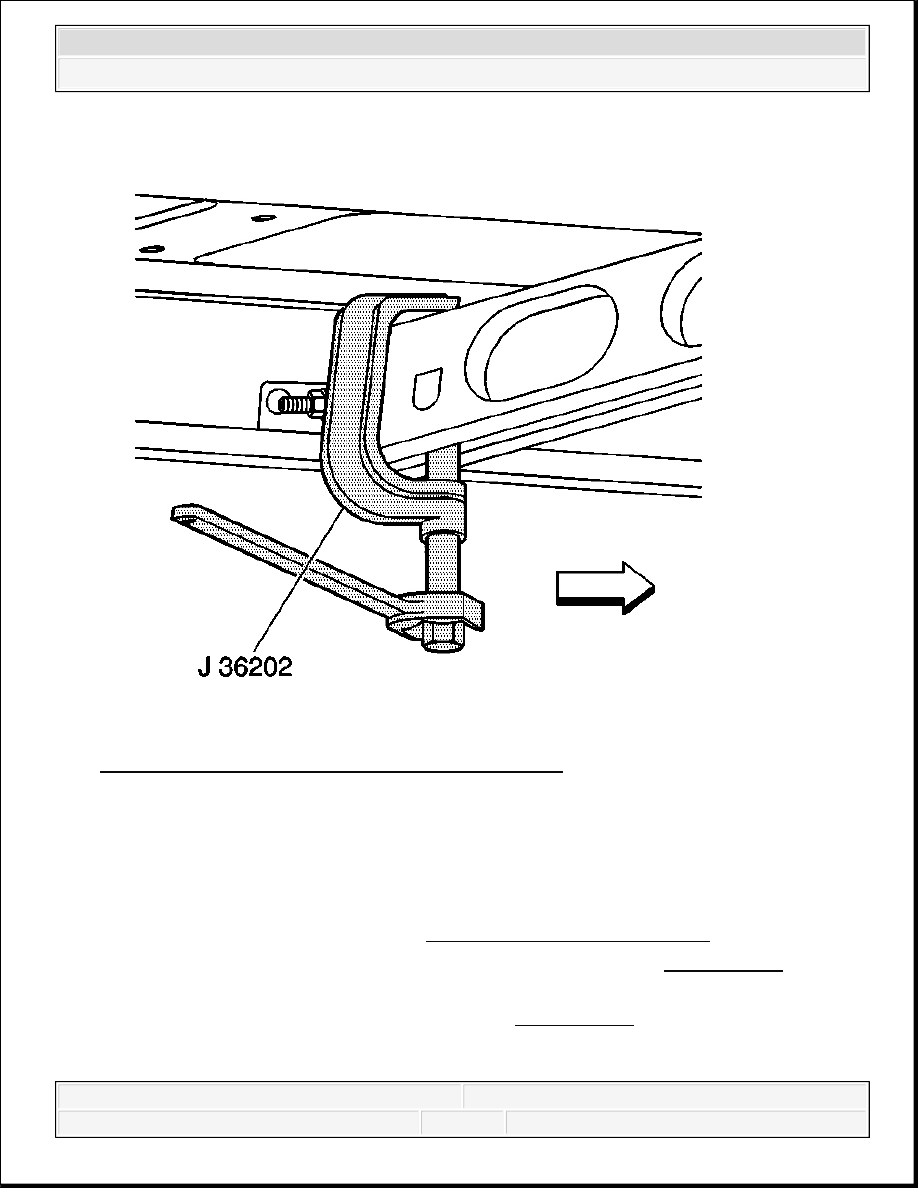
Fig. 36: J 36202, Adjustment Arm & Crossmember
Courtesy of GENERAL MOTORS CORP.
1. Raise and support the vehicle. Refer to Lifting and Jacking the Vehicle .
2. Install the J 36202 to the adjustment arm and the crossmember. See Special Tools.
3. Using the J 36202 , increase the tension on the adjustment arm until the load is removed
from the adjustment bolt and the adjuster nut. See Special Tools.
NOTE:
Use care when handling the torsion bars in order to avoid
chipping or scratching the coating. Damage to the coating will
result in premature failure of the torsion bars.
2008 Chevrolet Silverado 1500
2008 SUSPENSION Front Suspension - Cab & Chassis Sierra, Cab & Chassis Silverado, Sierra & Silverado
Content .. 2282 2283 2284 2285 ..