Content .. 2273 2274 2275 2276 ..
Chevrolet Silverado / GMC Sierra. Manual - part 2275

Fig. 6: View Of Stabilizer Shaft Insulator (2500, 3500)
Courtesy of GENERAL MOTORS CORP.
Callout
Component Name
Preliminary Procedure
1. Raise and support the vehicle. Refer to Lifting and Jacking the Vehicle .
2. Remove the engine shield, if equipped. Refer to Engine Shield Replacement .
1
Stabilizer Shaft Clamp Bolt (Qty: 2)
NOTE:
Refer to Fastener Notice .
2008 Chevrolet Silverado 1500
2008 SUSPENSION Front Suspension - Cab & Chassis Sierra, Cab & Chassis Silverado, Sierra & Silverado

LOWER CONTROL ARM BALL JOINT REPLACEMENT
Removal Procedure
1. Raise and support the vehicle. Refer to Lifting and Jacking the Vehicle .
2. Remove the tire and wheel assembly. Refer to Tire and Wheel Removal and
Installation .
3. Remove the lower control arm from the vehicle. Refer to Lower Control Arm
Replacement (1500) or Lower Control Arm Replacement (2500, 3500).
4. Place the lower control arm in a vise.
5. Using a chisel, remove the securing crimps from the ball joint body, if equipped.
6. Using a press, remove the ball joint from the lower control arm.
Installation Procedure
1. Install the ball joint using a press.
2. Place the lower control arm a bench vise.
3. Using a punch, install the crimps to the ball joint, if necessary. Use the replaced ball joint as
a reference.
4. Install the lower control arm in the vehicle. Refer to Lower Control Arm Replacement
(1500) or Lower Control Arm Replacement (2500, 3500)
5. Install the tire and wheel. Refer to Tire and Wheel Removal and Installation .
6. Remove the safety stand and lower the vehicle.
7. Verify the wheel alignment. Refer to Wheel Alignment Specifications .
STEERING KNUCKLE REPLACEMENT (2500, 3500)
Tighten: 50 N.m (37 lb ft)
2
Stabilizer Shaft Clamp
3
Stabilizer Shaft Insulator
Tip: Ensure the slit in the insulator is facing front of the vehicle when installed.
IMPORTANT: The following service procedure applies to vehicle equipped with
cast iron lower control arms only.
IMPORTANT: Use the outer flange of the ball joint in order to press the ball
joint into place.
2008 Chevrolet Silverado 1500
2008 SUSPENSION Front Suspension - Cab & Chassis Sierra, Cab & Chassis Silverado, Sierra & Silverado
Removal Procedure
1. Remove the tire and wheel. Refer to Tire and Wheel Removal and Installation .
2. Remove the wheel drive shaft, if equipped. Refer to Wheel Drive Shaft Replacement
(2500) or Wheel Drive Shaft Replacement (1500) .
3. Remove the wheel bearing and hub assembly. Refer to Front Wheel Hub, Bearing, and
Seal Replacement (2500) or Front Wheel Hub, Bearing, and Seal Replacement
(1500).
4. Remove the outer tie rod end from the knuckle.
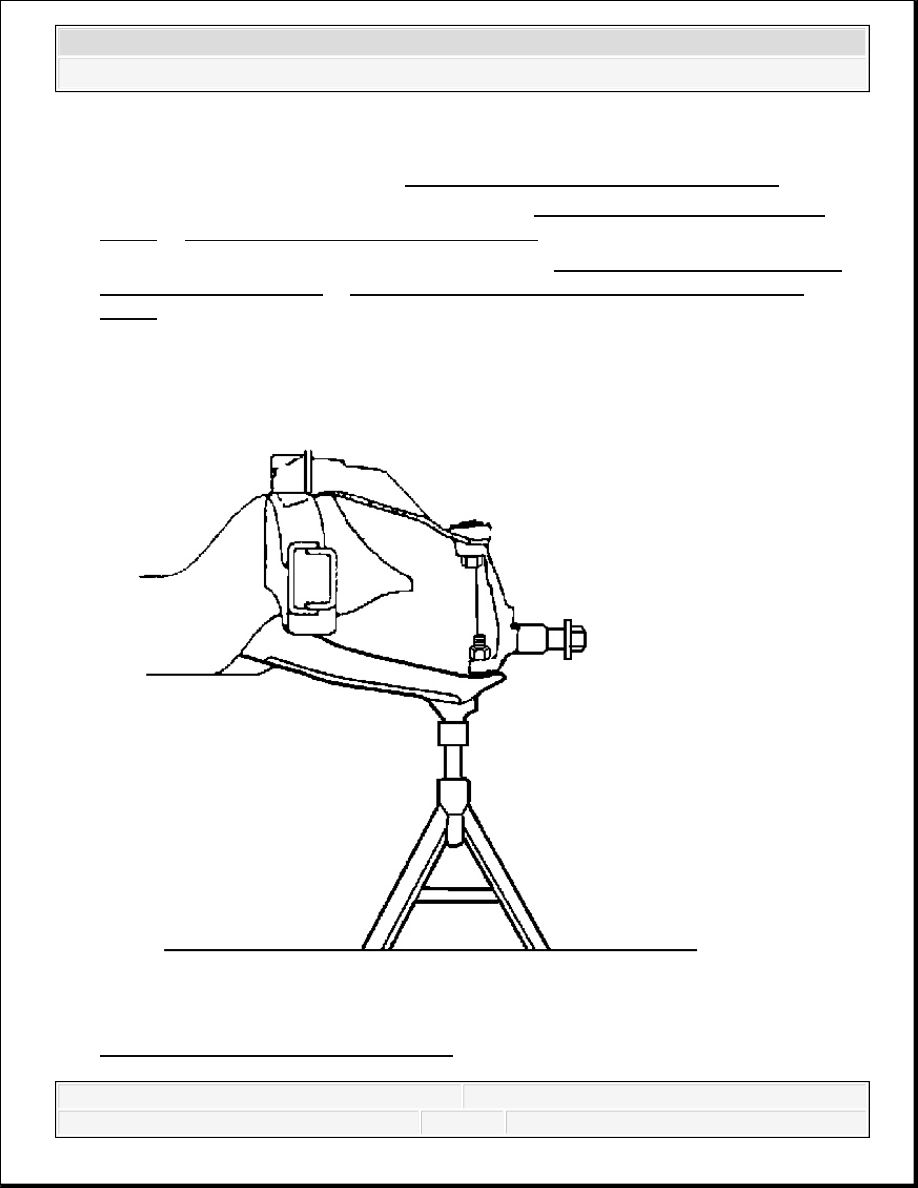
Fig. 7: Supporting Lower Control Arm
Courtesy of GENERAL MOTORS CORP.
2008 Chevrolet Silverado 1500
2008 SUSPENSION Front Suspension - Cab & Chassis Sierra, Cab & Chassis Silverado, Sierra & Silverado
5. Support the lower control arm.
6. Separate the upper ball joint from the knuckle. Refer to Upper Control Arm
Replacement (1500) or Upper Control Arm Replacement (2500, 3500).
7. Separate the lower ball joint from the knuckle. Refer to Lower Control Arm
Replacement (1500) or Lower Control Arm Replacement (2500, 3500).
8. Remove the knuckle from the vehicle.
Installation Procedure
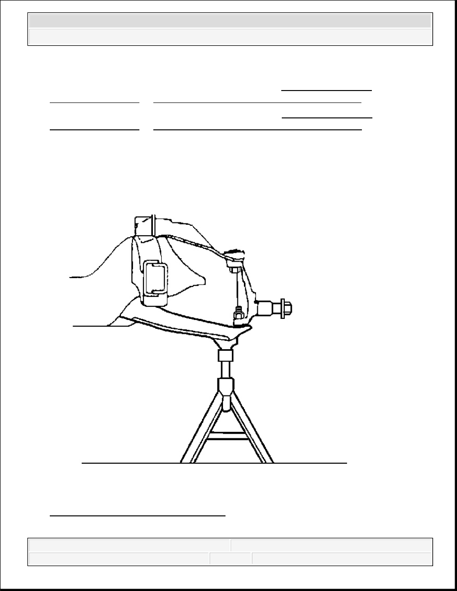
Fig. 8: Supporting Lower Control Arm
Courtesy of GENERAL MOTORS CORP.
2008 Chevrolet Silverado 1500
2008 SUSPENSION Front Suspension - Cab & Chassis Sierra, Cab & Chassis Silverado, Sierra & Silverado
Content .. 2273 2274 2275 2276 ..