Content .. 1635 1636 1637 1638 ..
Chevrolet Silverado / GMC Sierra. Manual - part 1637
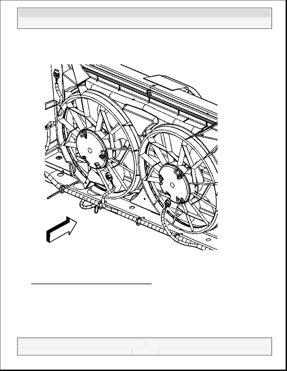
Fig. 94: Cooling Fan Electrical Connectors
Courtesy of GENERAL MOTORS CORP.
4. Connect the electrical connectors to the cooling fans.
5. Install the clip attaching the wiring harness to the shroud.
6. Install the transmission cooling line bolts to fan shroud.
Tighten: Tighten the bolts to 4 N.m (35 lb in).
2008 Chevrolet Silverado 1500
2008 ENGINE Engine Cooling - Cab & Chassis Sierra, Cab & Chassis Silverado, Sierra & Silverado

Fig. 95: View Of Surge Tank Inlet Hose & Clamp
Courtesy of GENERAL MOTORS CORP.
7. If necessary, install the surge tank inlet hose to the radiator.
8. If necessary, reposition the surge tank inlet hose clamp at the radiator.
2008 Chevrolet Silverado 1500
2008 ENGINE Engine Cooling - Cab & Chassis Sierra, Cab & Chassis Silverado, Sierra & Silverado
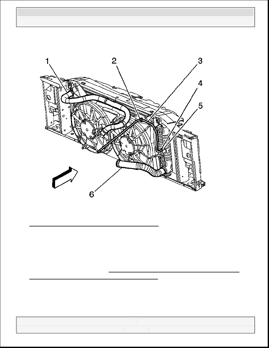
Fig. 96: Radiator, Inlet & Outlet Hose & Clamps
Courtesy of GENERAL MOTORS CORP.
9. Engage the radiator inlet hose clip (2) at the fan shroud.
10. Connect upper radiator hose from radiator.
11. Install air inlet duct.
12. Fill the cooling system. Refer to Cooling System Draining and Filling (Vac-N-Fill) or
Cooling System Draining and Filling (Static Fill)
TURBOCHARGER COOLANT BYPASS VALVE REPLACEMENT
Removal Procedure
2008 Chevrolet Silverado 1500
2008 ENGINE Engine Cooling - Cab & Chassis Sierra, Cab & Chassis Silverado, Sierra & Silverado
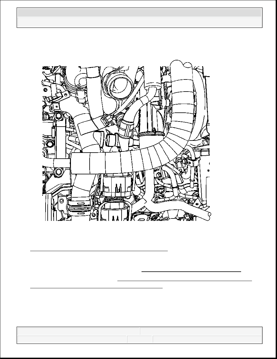
Fig. 97: View Of Turbocharger Coolant Inlet Hose
Courtesy of GENERAL MOTORS CORP.
1. Remove the intake manifold cover. Refer to Intake Manifold Cover Replacement .
2. Drain the cooling system. Refer to Cooling System Draining and Filling (Vac-N-Fill) or
Cooling System Draining and Filling (Static Fill).
3. Reposition the coolant inlet hose clamp.
4. Disconnect the turbocharger coolant inlet hose from the turbocharger bypass valve.
2008 Chevrolet Silverado 1500
2008 ENGINE Engine Cooling - Cab & Chassis Sierra, Cab & Chassis Silverado, Sierra & Silverado
Content .. 1635 1636 1637 1638 ..