Chery Tiggo T11 LHD. Manual - part 32


  Index      Chery     Chery Tiggo T11 LHD - service repair manual


Search            


Content   ..  30  31  32  33   ..


Chery Tiggo T11 LHD. Manual - part 32


T11 Service Manual                                        Chassis System


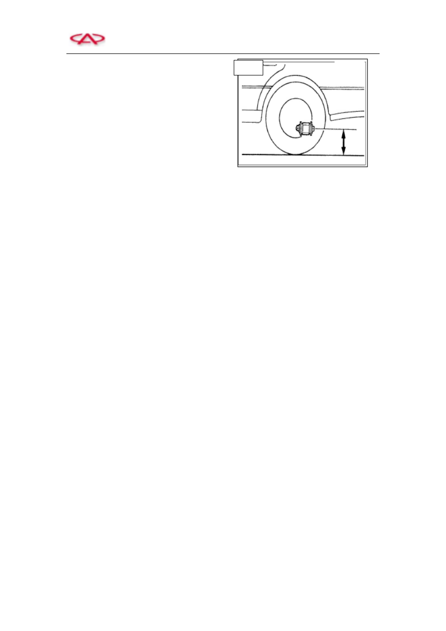
b. Rear measuring point   

Check  the  height  between  the  ground  and  the 

connecting  bolt  that  joins  the  rear  axle  to  the 

shock absorber. The body height of the left and 

right wheels shall be identical.   


Note: Prior to checking wheel alignment, firstly adjust the vehicle to specified height.     

If vehicle height does not conform to standard, inspect the front and rear suspension of the vehicle 

to confirm whether there exists damage or deformation.         

c. Inspect wheel bearing clearance, and replace front-wheel bearing if necessary.   

d. Inspect the status of wheel rim and tire.     

e. Inspect the loosening level of steering linkage and ball joint.     

f. Park the vehicle (without luggage or passengers) on a level ground.     

g. Shake the wheel and inspect the loosening status of front suspension.   

h. Inspect shock absorber to ensure its normal operation.     

a)  Inspect and avoid oil leakage. 

b)  Inspect the mounting bushing to avoid wear.       

c)  Inspect  the  damping  force  of  shock  absorber,  and  replace  if  not  conform  to 

specification.   

Note: fuel tank shall be half-full. Cooling water in radiator and the engine oil shall be at specified 

height. Tire jack and driver's tools shall be placed at designated location.     


Rear 

T11 Service Manual                                        Chassis System


2. Wheel Rim and Tire   

1)  Visual inspection   

Inspect the tire and wheel rim, if there exists 

crack,  damage,  deformation  or  other  defects, 

replace wheel or tire. As is shown in the right 

figure.     


    Tire Wear   

2)  Tire wear 

a.  Refer  to  the  standard  tire  figure  to 

inspect the tire thread depth of other 

parts. 

Minimum depth: 1.6mm   

Tire  for  snow  condition:  50%  of  the  thread 

depth   

b.  If  wear  indication  strip  appears,  the 

tire must be replaced.     


Tire Wear Point Indication 

3)  Tire abnormal wear     

Tire abnormal wear is shown in right figure.   


Tire Wear 


Both Side 

Wear 

Central Wear 

Toe-in and Toe-out Wire 

Single Side Wear 

Wear Points Indication 

Wear Points Indication 


T11 Service Manual                                        Chassis System


Refer to the table below for possible causes and remedies.   


        Possible causes   

        Remedies   


(a) 

Inadequate tire pressure (both sides wear)   

High speed turning   

Tire swap is not performed   

Measure and adjust tire pressure.     

Reduce vehicle speed.     

Perform tire swap   


(b) 

Excessive high pressure of tire (central wear)   

Tire swap is not performed   

Measure and adjust tire pressure     

Perform tire swap   

(c) 

Incorrect toe-in 

Adjust toe-in   


(d) 

Incorrect camber angle or caster angle 


Suspension system malfunction   

Tire unbalance   

Brake drum or disc out of round   

Other mechanical problems   

Tire swap is not performed   

Adjust, repair or replace axle and parts of 

suspension system   

Repair or replace   

Perform tire dynamic balancing or replace the tire   

Calibrate or replace   

Correct or replace   

Perform tire swap   

4)  Precautions of wheel rim and tire   

a.  Never use defective wheel rim or tire. 

b.  Aluminum alloy rim is easily to be scratched, therefore, use soft cloth but never use steel 

brush when cleaning. And never contact the rim with boiling water when washing the 

vehicle by steam.   

c.  If abrasive compound (such as turbid water and ground mud) adheres to aluminum alloy 

rim, please rinse the rim with neutral detergent as soon as possible to avoid damage.     

5)  Tire replacement   

a.  Prior to installing tire valve, firstly inspect the wheel to see whether the valve port of the 

wheel is smooth and burr-free. Then apply  glycerol to the valve rubber surface  or  soak 

the valve into glycerol solution. Finally use special tools to apply a pressure of 200-400N 

to press the locating ring on the valve to pass through the wheel valve port, thus it shall 

be  deemed  as  being  installed  to  proper  position  (Soap  water  is  allowed  to  substitute 

glycerol).     

b.  Prior  to  installing  tire,  apply  glycerol  or  soap  water  at  the  periphery  of  tire  bead. 

Meanwhile,  if  there  is  slight  mark  on  the  wheel  rim,  please  align  the  tire  uniformity 

testing  mark  to  the  rim  slight  mark.    If  there  is  no  slight  mark,  align  the  tire  dynamic 

balance  testing  mark  to  the  position  of  wire  valve.    If  there  is  no  slight  mark  on  the 

wheel rim, and the wire has static balancing test mark instead of a dynamic one, align the 

wheel valve to static balance testing mark.     


T11 Service Manual                                        Chassis System


6)  Tire pressure   

Inspect  all  of  the  tire  pressures  (including 

spare  tire)  via  barometer,  and  adjust  if 

necessary. 

Inflate 

the 

tire 

strictly 

in 

accordance with specified pressure value, and 

the  tire  pressure  shall  not  exceed  the  rated 

pressure by 10% during inflating process. The 

rated  inflation  pressure  of  the  spare  tire  shall 

be  2.5bar  when  the  spare  tire  assembly  is 

separately installed, and the spare tire shall be 

stored  separately  from  the  other  4  wheels. 

Prior to aligning the wheels, inspect and adjust 

the tire pressure: the front wheel pressure shall 

be  2.0bar;  the  rear  wheel  pressure  shall  be 

2.0bar, as shown in the right figure. 


Inspection of Tire Pressure 


7)  Air leakage   

Confirm whether there exists tire valve leakage, 

as shown in the right figure.     


8)  Tire unflatness inspection   

a.  Lift  the  vehicle,  and  cautiously 

support it. 

b.  Fix  a  micrometer  (Φ10)  with  a 

cylindrical contact tip to the rim edge, 

then  measure  the  unflatness  depth,  as 

shown in the figure.   

c.  Replace the wheel rim if necessary.     


Inspection of Tire Unflatness 

Tire Valve 

Tire 


Content   ..  30  31  32  33   ..