Chery Tiggo. Manual - part 440


  Index      Chery     Chery Tiggo - service repair manual 2009 year


Search            


Content   ..  438  439  440  441   ..


Chery Tiggo. Manual - part 440


Rear Door

Removal & Installation

1. Disconnect the negative battery cable.

2. Disconnect the inner electrical harness connector

on the rear door.

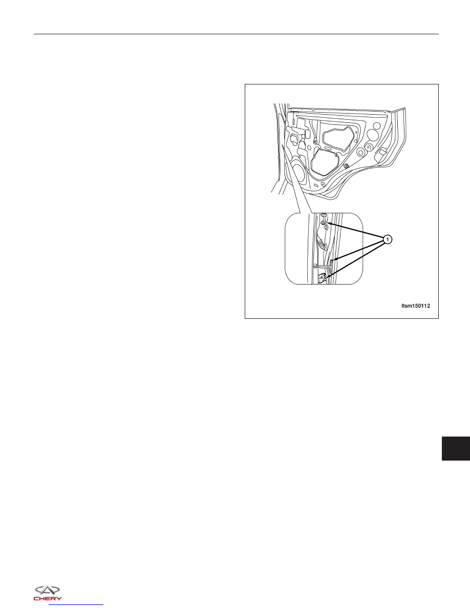
3. Remove the mounting bolts (1) from the rear door

hinge.

4. Remove the rear door assembly.

5. Installation is in the reverse order of removal.

Disassembly

1. Remove the bolts to remove the bezel for the inside door handle.

2. Pry out the window regulator switch and pull out the electrical harness.

3. Remove the door trim panel.

4. Remove the mounting bolts for the inside door handle to remove the handle.

5. Remove the protective film from the rear door.

6. Lower the glass to a proper position, remove the set bolts, move the glass to the bottom of the door, and then

remove the door glass.

7. Remove the mounting bolts for the glass guide rail.

DOORS

LTSM150112

15


8. Remove the mounting bolts (1) from the window

regulator.

9. Remove the lock mounting screws with an internal

spline socket.

10. Loosen the pull rod from the door handle, pull out

the electrical harness, and then remove the lock.

11. Remove the rear door outside handle.

• Remove the mounting bolts of the handle seat

with hexagon spline wrench from one side of
the shield.

12. Remove the handle seat.

• Remove the outside handle.

13. Remove the weather strip from the door opening.

14. Disconnect the inner harness of the door from out-

side.

Assembly

Assemble in the reverse order of disassembly.

Rear Door Adjustment

1. Adjust the door gap with a spacer gauge.

• The gap between the rear door and the trian-

gle window should be 8 ± 1.5 mm

• The gap between the rear door and the side

fender should be 6 ± 1 mm

• The gap between the rear door and the door-

sill should be 6 ± 1 mm

• The overall levelness when measured with a

magnet should be 0-0.5 mm as shown by the
arrow

2. Install the nuts (Part Number: Q32008, 2 pcs both

upper and lower) into the body for 2-3 turns,
tighten with pneumatic wrench. Torque: 35 ± 3
N·m.

Check for the following after repair:
• Any scratches from reassembly

• Whether the bolts and nuts are assembled properly

• Whether the bolts and nuts are properly tightened

• Whether the gap between rear door and side fender and the levelness are within the specifications

• Whether the edge of back door is 0-0.5 mm higher than the side fender.

DOORS

LTSM150118

LTSM150119


Replacing Rear Door Hinge

1. Remove the door check bolts.

2. Support the door.

3. Remove the four retaining bolts from the upper and lower hinges, and then remove the hinges.

Back Cargo Door

Removal & Installation

1. Remove the two back cargo door bolts connecting the back door and hinge.

(Tighten: Bolts connecting the back door and hinge to 50 ± 5 N·m)
(Tighten: Bolts connecting the hinge and body to 36 ± 4 N·m)

2. Disconnect the wiring harness electrical connector.

3. Remove the two mounting bolts (1) of the back

cargo door stopper on body.
(Tighten: Bolts connecting the back cargo door
stopper bracket and body to 27 N·m)

4. Remove the back cargo door.

5. Installation is in the reverse order of removal.

Disassembly

1. Remove the back cargo door panel.

2. Remove the rear wiper motor (See Rear Wiper

Motor Removal & Installation in Section 15 Body &
Accessories).

3. Remove the protective film from the back cargo

door.

4. Remove mounting bolts, pull out the harness.

5. Remove the outside handle mounting bolts (1) from

one side of the door panel.

DOORS

LTSM150113

LTSM150121

15


6. Remove the rod from the door handle from the

door lock body, remove the outer handle of back
cargo door.

7. Remove the back cargo door lock.

8. Pull out the connector for the wiring harness.

9. Remove the lock.

10. Remove the high mounted stop lamp assembly (1).

11. Remove the rear fog lamp assembly.

12. Remove the spare tire support.

DOORS

LTSM150122

LTSM150123


Content   ..  438  439  440  441   ..