Chery Tiggo. Manual - part 438


  Index      Chery     Chery Tiggo - service repair manual 2009 year


Search            


Content   ..  436  437  438  439   ..


Chery Tiggo. Manual - part 438


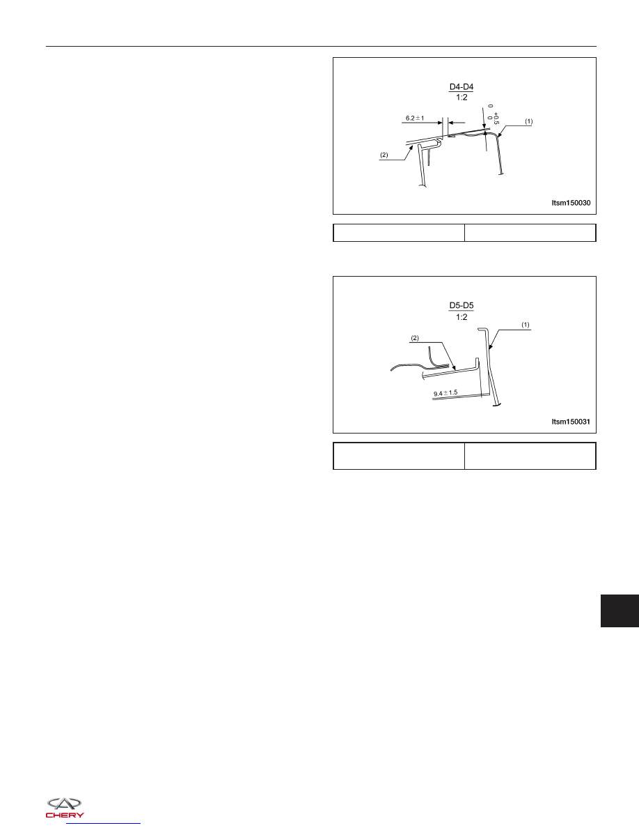
Cross section D4-D4, requirements for clearance and
levelness.

Cross section D5-D5, requirements for clearance and
levelness.

1 - Rear Back Door

2 - Rear Headlight

1 - Right Section Of Rear

Bumper

2 - Middle Section Of Rear

Bumper

BODY DIMENSIONS

LTSM150030

LTSM150031

15


BUMPERS

Front Bumper

Removal & Installation

1. Remove the left and right headlamp (See Headlamp Removal & Installation in Section 15 Body & Accessories).

2. Remove the three front bumper mounting bolts (1).

3. Remove the front bumper side mounting bolts and the connecting bolts (3) from the front wheel house.

4. Raise the vehicle and remove the mounting bolts (2) under the front bumper.

5. Disconnect the front fog light electrical connectors and remove the front bumper.

6. Installation is in the reverse order of removal.

LTSM150074


DOORS

Specification

Torque Specifications

DESCRIPTION

TORQUE (N·m)

Left/Right Front Door Upper Hinge to Body Bolts

36 ± 4

Left/Right Front Door Upper Hinge to Door Bolts

36 ± 4

Left/Right Front Door Lower Hinge to Body Bolts

36 ± 4

Left/Right Front Door Lower Hinge to Door Bolts

36 ± 4

Left/Right Rear Door Upper Hinge to Body Bolts

36 ± 4

Left/Right Rear Door Upper Hinge to Door Bolts

36 ± 4

Left/Right Rear Door Lower Hinge to Body Bolts

36 ± 4

Left/Right Rear Door Lower Hinge to Door Bolts

36 ± 4

Back Door Upper Hinge to Body Bolts

36 ± 4

Back Door Upper Hinge to Door Bolts

50 ± 5

Back Door Lower Hinge to Body Bolts

35 ± 3

Back Door Lower Hinge to Door Bolts

50 ± 5

Left Hood Hinge to Body Bolts

23 ± 2

Left Hood Hinge to Hood Bolts

23 ± 2

Right Hood Hinge to Body Bolts

23 ± 2

Right Hood Hinge to Hood Bolts

23 ± 2

Rear Mounting Bracket of Front Fender to Body Bolts

10 ± 1

Left/Right Front Fender to Body Bolts

10 ± 1

Radiator Support to Body Bolts

10 ± 1

15


Front Door

Removal & Installation

1. Disconnect the negative battery cable.

2. Disconnect the inner harness electrical connector

on the front door.

3. Remove the mounting bolts (1) from the front door

hinge.

4. Remove the front door assembly.

5. Installation is in the reverse order of removal.

Disassembly

1. Turn the ignition switch off.

2. Using a small trim stick, remove the pull handle

cover (1) from the pull handle (2).

DOORS

LTSM150111

LTSM150139


Content   ..  436  437  438  439   ..