Chery Tiggo. Manual - part 417
 

  Index      Chery     Chery Tiggo - service repair manual 2009 year


Search            


Content   ..  415  416  417  418   ..


Chery Tiggo. Manual - part 417


Diagnostic Procedure

1.

CHECK DTC

• Turn ignition switch on, with the scan tool, view and erase stored DTCs in the IC.

• Turn ignition switch off, and wait a few seconds, then turn ignition switch on.

• With the scan tool, view DTCs in the IC.

Is DTC U0303 present?

Yes

>>

Go to the next step.

No

>>

The conditions that caused this DTC to set are not present at this time (See Intermittent DTC Trouble-

shooting in Section 15 Body & Accessories for more information).

2.

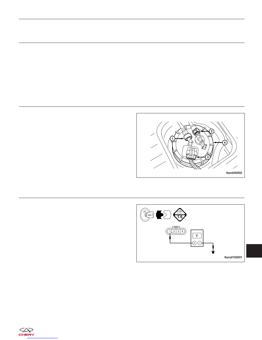
CHECK FUEL LEVEL SENSOR ELECTRICAL CONNECTOR

• Turn ignition switch off.

• Disconnect the fuel level sensor and fuel pump

assembly electrical connector (3).

• Inspect the electrical connector for damage.

Is the electrical connector OK?

Yes

>>

Go to the next step.

No

>>

Repair or replace the electrical connector

as necessary.

3.

CHECK FUEL LEVEL SENSOR REFERENCE VOLTAGE

• Turn ignition switch on.

• Check the fuel level sensor reference voltage

between the fuel level sensor connector B-032, ter-
minal 1 and ground.

• The voltage (less than 1 V) should exist.

Is there voltage present?

Yes

>>

Go to step 5.

No

>>

Go to the next step.

DIAGNOSIS & TESTING

LTSM040002

LTSMD150001

15


4.

CHECK FUEL LEVEL SENSOR CIRCUIT FOR OPEN OR SHORT

• Turn ignition switch off.

• Disconnect the IC connector.

• Check harness for a short to ground.

FUEL LEVEL SENSOR

TERMINAL

GROUND

1

Ground

• Check for continuity between the following terminals:

FUEL LEVEL

SENSOR

TERMINAL

IC TERMINAL

CONTINUITY

1

21

Yes

• Continuity should exist.

• Check the harness for a short to power.

Is the check result normal?

Yes

>>

Go to the next step.

No

>>

Repair or replace the fuel level sensor supply circuit as necessary.

5.

CHECK FUEL LEVEL SENSOR GROUND CIRCUIT

• Using a 12 V test light connected to battery (+), probe fuel level sensor ground circuit.

Does the test light illuminate brightly?

Yes

>>

Go to the next step.

No

>>

Repair or replace the fuel level sensor ground circuit for an open.

DIAGNOSIS & TESTING


6.

CHECK FUEL LEVEL SENSOR RESISTANCE

• Turn ignition switch off.

• Check fuel level sensor as follows:

FUEL GAUGE POINTER

POSITION

TANK (LITERS)

SENDER RESISTANCE

(OHM)

POINTER TOLERANCE

EMPTY

5

283

±3 °

RESERVE

11

189

±3 °

1/4

16.5

137

±3 °

1/2

28

89

±3 °

3/4

39.5

62

±3 °

FULL

51

40

±3 °

Is the check result normal?

Yes

>>

Go to the next step.

No

>>

Replace the fuel level sensor.

7.

CHECK DTC

• With the X-431 scan tool, read IC DTCs.

• Refer to ⬙DTC Confirmation Procedure⬙.

Is the DTC U0303 still present?

Yes

>>

Replace the IC.

No

>>

The system is now operating properly.
Reassemble the vehicle and verify the customers complaint is repaired.

DIAGNOSIS & TESTING

15


ON-VEHICLE SERVICE

Instrument Cluster

Removal & Installation

1. Disconnect he negative battery cable.

2. Carefully remove the instrument cluster trim panel.

3. Remove the instrument cluster screws (1).

(Tighten: Instrument cluster screws to 5 N·m)

4. Disconnect the instrument cluster electrical connector.

5. Remove the instrument cluster.

6. Installation is in the reverse order of removal.

LTSM150085


Content   ..  415  416  417  418   ..