Index Chery Chery Tiggo - service repair manual 2009 year
Search
Content .. 376 377 378 379 ..
Chery Tiggo. Manual - part 378
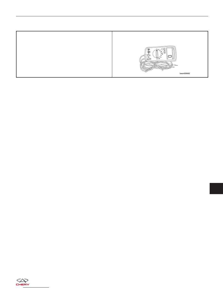
Special Tools
Digital Multimeter
Fluke 15B & 17B
GENERAL INFORMATION
13