Chery Tiggo. Manual - part 379


  Index      Chery     Chery Tiggo - service repair manual 2009 year


Search            


Content   ..  377  378  379  380   ..


Chery Tiggo. Manual - part 379


Removal & Installation

NOTE :
The blower motor is located on the bottom of the HVAC housing. The blower motor can be removed from the vehicle
without having to remove the HVAC housing.

1. Disconnect the blower motor electrical connector.

2. Remove the glove box (See Instrument Panel Removal & Installation in Section 15 Body & Accessories).

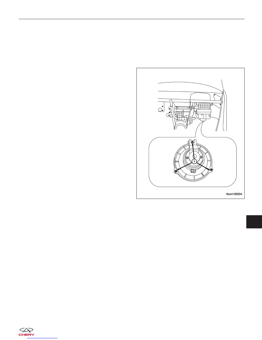
3. Remove the mounting bolts (1) for the blower

motor.

4. Remove the blower motor.

5. Installation is in the reverse order of removal.

ON-VEHICLE SERVICE

LTSM130004

13


SYSTEM PLUMBING

GENERAL INFORMATION

13-33

Description

13-33

Operation

13-33

Specifications

13-33

Special Tools

13-34

DIAGNOSIS & TESTING

13-35

Mechanical Problems

13-35

Temperature Control

13-35

A/C Compressor Noise Testing

13-35

Refrigerant System Leaks

13-36

Refrigerant System Empty

13-36

Refrigerant System Low

13-36

ON-VEHICLE SERVICE

13-37

A/C System Evacuation and Recharge

13-37

Connecting Refrigerant Recovery/
Recycling Station

13-37

A/C System Evacuation

13-38

A/C System Recharge

13-38

Compressor

13-39

Description

13-39

Operation

13-39

Removal & Installation - 1.6L & 1.8L &
2.0L

13-39

Removal & Installation - 2.4L

13-41

Evaporator

13-42

Description

13-42

Operation

13-42

Removal & Installation

13-42

Condenser

13-42

Description

13-42

Operation

13-42

Removal & Installation

13-43

Accumulator

13-43

Description

13-43

Operation

13-43

Removal & Installation

13-43

Liquid Line

13-44

Description

13-44

Operation

13-44

Removal & Installation

13-44

Suction Line

13-45

Description

13-45

Operation

13-45

Removal & Installation

13-45

Heater Core

13-47

Description

13-47

Operation

13-47

Removal & Installation

13-47


GENERAL INFORMATION

Description

The A/C refrigerant lines and pipes are used to carry the refrigerant between the various A/C system components.

Any kinks or sharp bends in the refrigerant lines and hoses will reduce the capacity of the entire A/C system and can
reduce the flow of refrigerant within the system.

Operation

High pressure is produced in a refrigerant system when the A/C compressor is operating. Extreme care must be
exercised to make sure that each of the refrigerant system connections is pressure-tight and leak free. It is a good
practice to inspect all flexible hose refrigerant lines at least once a year to make sure they are in good condition and
properly routed. Depending on vehicle, model and market application, refrigerant lines are connected to each other or
other A/C system components with block-type or quick-connect type fittings. To ensure the integrity of the refrigerant
system, O-rings and/or gaskets may be used to seal the refrigerant system connections. The refrigerant lines and
hoses cannot be repaired and must be replaced if leaking or damaged.

WARNING!

The A/C system contains refrigerant under high pressure. Repairs should only be performed by qualified service
personnel. Serious or fatal injury may result from improper service procedures.
If accidental A/C system discharge occurs, ventilate the work area before resuming service. Large amounts of
refrigerant released in a closed work area will displace the oxygen and cause suffocation and serious or fatal
injury.

CAUTION:
Never add R-12 to a refrigerant system designed to use R-134a. Do not use R-12 equipment or
parts on an R-134a A/C system. These refrigerants are not compatible and damage to the A/C sys-
tem will result.

CAUTION:
Never use R-12 refrigerant oil in an A/C system designed to use R-134a refrigerant oil. These refrig-
erant oils are not compatible and damage to the A/C system will result.

CAUTION:
Do not run the engine with a vacuum pump in operation or with a vacuum present within the A/C
system. Failure to follow this caution will result in serious A/C compressor damage.

CAUTION:
Do not overcharge the refrigerant system. Overcharging will cause excessive compressor head
pressure and can cause compressor noise and A/C system failure.

Specifications

Torque Specifications

DESCRIPTION

TORQUE (N·m)

A/C Compressor Bracket Bolts

40

A/C Compressor Line Bolts

20

13


A/C Refrigerant Charge Specifications

DESCRIPTION

CAPACITY (kg)

R-134a Refrigerant

0.700

A/C Oil Specifications

DESCRIPTION

CAPACITY (ml)

Compressor

150

Condenser, Accumulator, Lines

15

Evaporator

30

Special Tools

Refrigerant Recovery/Recycling Station

GENERAL INFORMATION


Content   ..  377  378  379  380   ..