Chery Tiggo. Manual - part 376


  Index      Chery     Chery Tiggo - service repair manual 2009 year


Search            


Content   ..  374  375  376  377   ..


Chery Tiggo. Manual - part 376


GENERAL INFORMATION

Description

The Heating, Ventilation and Air Conditioning (HVAC) system uses a combination of electrical and vacuum controls.
These controls provide the vehicle operator with a number of setting options to help control the climate and comfort
within the vehicle. Refer to the owner’s manual in the vehicle glove box for more information on the suggested oper-
ation and use of these controls.
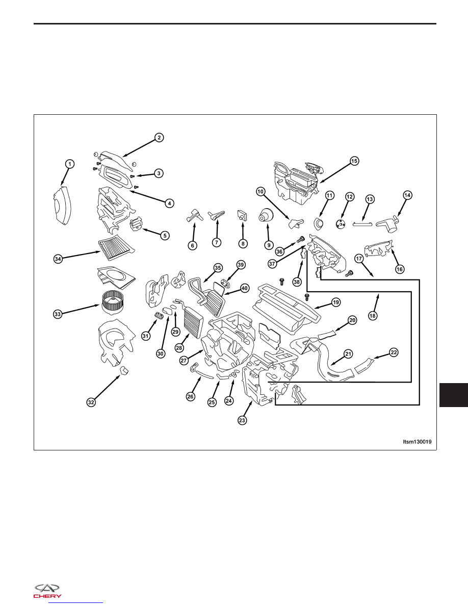
LTSM130019

13


1 - Inlet Shell Shield

2 - Inlets Shrouds

3 - Bolt (M6)

4 - Inlet Shell Assembly

5 - Recirculation Door Actuator

6 - Mixed Door Lever

7 - Defrost Door Lever

8 - Water Hose Clamp

9 - Blower Control Dial

10 - Defrost Door Linkage

11 - Mode Door Dial

12 - Plastic Washer

13 - Mode Door Dial Linkage

14 - Mode Door Dial Lever

15 - Evaporator Assembly

16 - HVAC Control Panel

17 - Temperature Control Dial Cable

18 - Mode Door Cable

19 - Outlet Assembly

20 - Clamp

21 - Left Outlet

22 - Right Outlet

23 - Evaporator Assembly Upper Cover

24 - Drain Inner Hose Assembly

25 - Rubber Drain Inside Hose

26 - Rubber Drain Outside Hose

27 - Evaporator Assembly Lower Cover

28 - Evaporator Core

29 - Sealed Gasket

30 - Sponge

31 - Expansion Valve

32 - Blower Motor Resistor

33 - Blower Motor

34 - HVAC Filter

35 - Heater Core

36 - HVAC Control Panel Bolt

37 - HVAC Control Panel

38 - Clamp

39 - Water Hose Sealed Gasket

40 - Sponge

GENERAL INFORMATION

LTSM130019


Operation

The A/C heater control module panel is located on the instrument panel inboard of the steering column and above
the radio. The A/C heater control panel contains a rotary-type temperature control dial (1), a rotary-type mode control
switch dial (3), a rotary-type blower motor speed control switch (2) and an air conditioning compressor push button
switch (6).

Temperature Control Dial

Increases or decreases the set temperature.

Recirculation Switch

• When the recirculation switch is ON, the switch indicator turns ON, and air inlet is set to recirculation.

• When recirculation switch is OFF, air inlet is set to fresh. The recirculation mode can be re-entered by pressing

the recirculation switch again.

Rear Window Defogger Switch

Controls the operation of the rear window defogger.

A/C Switch

Controls the A/C compressor ON and OFF function.

Mode Control Dial

Controls the direction of the air flow through the air discharge outlets.

Blower Control Dial

Manually controls the four blower speeds and the ON and OFF function.

1 - Temperature Control Switch

2 - Blower Switch

3 - Mode Control Switch

4 - Rear Window Defogger Switch

5 - Recirculation Switch

6 - A/C Switch

GENERAL INFORMATION

LTSM130009

13


Discharge Air Flow

1. Panel Mode

Air comes from the outlets in
the instrument panel. Each
of these outlets can be
individually adjusted to direct
the flow of air.

2. Bi-Level Mode

Air comes from both the
instrument panel outlets and
the floor outlets.

3. Floor Mode

Air comes from the floor
outlets. A slight amount of air
is directed through the
defrost and side window
demister outlets.

4. Defrost & Floor Mode

Air comes from the floor,
defrost and side window
demister outlets. This mode
works best in cold or snowy
conditions.

5. Defrost Mode

Air comes from the
windshield and side window
demister outlets. Use this
setting when necessary to
defrost your windshield and
side windows.

GENERAL INFORMATION

LTSM130012


Content   ..  374  375  376  377   ..