Chery Tiggo. Manual - part 363


  Index      Chery     Chery Tiggo - service repair manual 2009 year


Search            


Content   ..  361  362  363  364   ..


Chery Tiggo. Manual - part 363


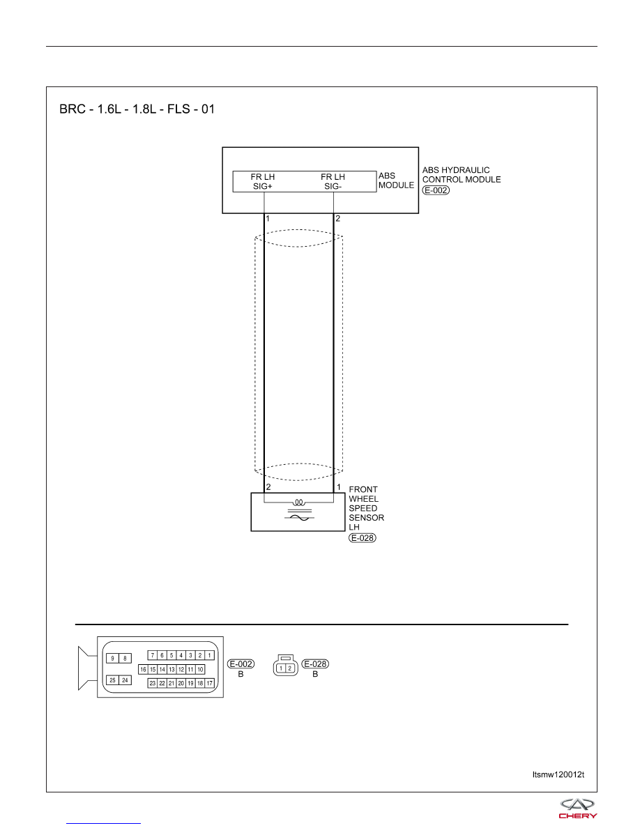
C1200 - Left Front Wheel Speed Sensor Circuit Open or Shorted

DIAGNOSIS & TESTING

LTSMW120012T


DIAGNOSIS & TESTING

LTSMW120004T

12


On Board Diagnostic Logic
• Self-diagnosis detection logic.

DTC NO.

DTC DEFINITION

DTC DETECTION

CONDITION

DTC SET

CONDITION

POSSIBLE CAUSE

C1200

Left front wheel

speed sensor circuit

open or shorted

• Ignition switch:
ON

• Vehicle: Running

ABS module
detected that the
Left Front wheel
speed sensor input
signal to ABS
module is open or
shorted.

• Left Front wheel
speed sensor

• Harness is open or
shorted

• ABS module

DTC Confirmation Procedure:

Before performing the following procedure, confirm that battery voltage is more than 12 V.

• Turn ignition switch off.

• Connect the X-431 scan tool to the Data Link Connector (DLC) - use the most current software available.

• Turn ignition switch on.

• With the scan tool, record and erase stored DTCs in the ABS module.

• Cycle the ignition switch from off to on.

• Start the engine and warm it to normal operating temperature.

• Turn ignition switch off and wait for a few seconds.

• Start the engine. With the scan tool connected to the DLC, drive the vehicle over 40 km/h (25 mph).

NOTE :
Vehicle must be driven above 40 km/h (25 mph) for fault setting conditions to be met.
• With the scan tool select: View ABS Data Stream and DTC.

• If the DTC is detected, the DTC condition is current. Go to Diagnostic Procedure - Step 1.

• If the DTC is not detected, the DTC condition is intermittent (See Diagnostic Help and Intermittent DTC Trou-

bleshooting in Section 12 Brakes for more information).

• Erase all codes and test drive the vehicle to verify the repair is complete.

NOTE :
While performing electrical diagnosis & testing, always refer to the electrical schematics for specific circuit
and component information.

Diagnostic Procedure

1.

CHECK ABS MODULE DTC

• With the scan tool select: View ABS Data Stream.

• With an assistant driving the vehicle, check the following data stream list items while driving the vehicle over 40

km/h (25 mph).

Left Front Wheel Speed

Right Front Wheel Speed

Left Rear Wheel Speed

Right Rear Wheel Speed

• With the scan tool, read active DTCs in the ABS module.

Is DTC C1200 present and the Left Front Wheel Speed signal abnormal?

Yes

>>

Go to the next step.

No

>>

The condition that caused this DTC to set is currently not present (See Diagnostic Help and Intermit-

tent DTC Troubleshooting in Section 12 Brakes for more information).

DIAGNOSIS & TESTING


2.

CHECK LEFT FRONT WHEEL SPEED SENSOR ELECTRICAL CONNECTOR

• Turn ignition switch off.

• Disconnect the wheel speed sensor (1) electrical

connector.

• Inspect the wheel speed sensor electrical connector

for damage.

Is the electrical connector OK?

Yes

>>

Go to the next step.

No

>>

Repair or replace the electrical connector

as necessary.

3.

CHECK LEFT FRONT WHEEL SPEED SENSOR REFERENCE SIGNAL CIRCUIT

• Turn ignition switch on.

• Measure the sensor reference voltage between ter-

minal 2 of the wheel speed sensor connector, ter-
minal side and ground.

• Voltage should exist (2.0 - 4.0 V).

Is the proper voltage present?

Yes

>>

Go to the next step.

No

>>

Repair or replace the circuit for an open,

short to ground or short to battery in connector or
harness.

4.

CHECK LEFT FRONT WHEEL SPEED SENSOR RESISTANCE

• Check the wheel speed sensor resistance between

the sensor terminals 1 and 2, component side.

Is the sensor resistance 700 - 1500 ohms?

Yes

>>

Go to the next step.

No

>>

Replace the Left Front wheel speed

sensor.

DIAGNOSIS & TESTING

PZSMD120001

LTSMD120003

VISMD120005

12


Content   ..  361  362  363  364   ..