Index Chery Chery Tiggo - service repair manual 2009 year
Search
Content .. 360 361 362 363 ..
Chery Tiggo. Manual - part 362
DIAGNOSIS & TESTING
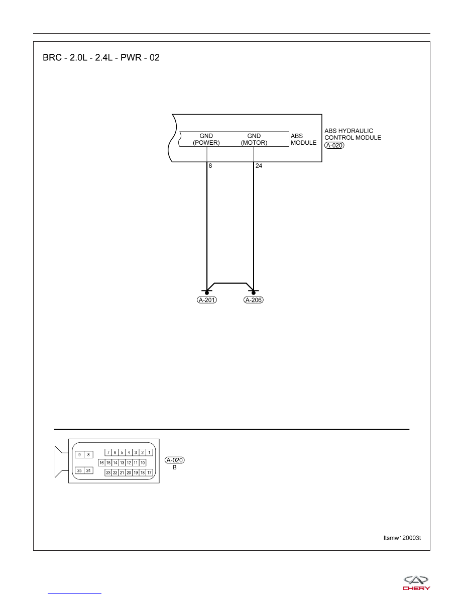
LTSMW120003T